参数资料
| 型号: | ISL6561CR-T |
| 厂商: | Intersil |
| 文件页数: | 17/26页 |
| 文件大小: | 0K |
| 描述: | IC CTRLR PWM MULTIPHASE 40-QFN |
| 标准包装: | 4,000 |
| 应用: | 控制器,Intel VR10X |
| 输入电压: | 3 V ~ 12 V |
| 输出数: | 4 |
| 输出电压: | 0.84 V ~ 1.6 V |
| 工作温度: | 0°C ~ 70°C |
| 安装类型: | 表面贴装 |
| 封装/外壳: | 40-VFQFN 裸露焊盘 |
| 供应商设备封装: | 40-QFN(6x6) |
| 包装: | 带卷 (TR) |
�� �
�
�ISL6561�
�tracks� the� lower� MOSFET� or� inductor� temperature.� The�
�value� of� K� T� is� typically� between� 75%� and100%.� K� TC� is� the�
�temperature� dependant� transconductance� of� internal�
�compensation� circuit.� Its� vaule� is� designed� as� 1� μ� A/V/°C.� The�
�temperature� coefficient� of� MOSFET� r� DS(ON)� or� Inductor�
�DCR� is� given� by� α� .� This� is� the� ratio� of� the� change� in�
�resistance� and� the� change� in� temperature.� Resistance� is�
�normalized� to� the� value� at� 25°C� and� the� value� of� α� is�
�typically� between� 0.35%/°C� and� 0.50%/°C.� For� copper�
�wound� inductors,� α� is� 0.39%/°C.�
�According� to� Equation� 13,� a� voltage� regulator� with� 80%�
�thermal� coupling� coefficient� between� the� controller� and� lower�
�MOSFET� and� 0.4%� /°C� temperature� coefficient� of� MOSFET�
�r� DS(ON)� requires� a� 5k� ?� TCOMP� resistor.�
�Initialization�
�Prior� to� converter� initialization,� proper� conditions� must� exist�
�on� the� enable� inputs� and� VCC.� When� the� conditions� are� met,�
�the� controller� begins� soft-start.� Once� the� output� voltage� is�
�within� the� proper� window� of� operation,� PGOOD� asserts�
�logic� 1.�
�Enable� and� Disable�
�While� in� shutdown� mode,� the� PWM� outputs� are� held� in� a�
�high-impedance� state� to� assure� the� drivers� remain� off.� The�
�following� input� conditions� must� be� met� before� the� ISL6561� is�
�released� from� shutdown� mode.�
�1� -� The� bias� voltage� applied� at� VCC� must� reach� the� internal�
�power-on� reset� (POR)� rising� threshold.� Once� this� threshold�
�is� reached,� proper� operation� of� all� aspects� of� the� ISL6561� is�
�guaranteed.� Hysteresis� between� the� rising� and� falling�
�thresholds� assure� that� once� enabled,� the� ISL6561� will� not�
�inadvertently� turn� off� unless� the� bias� voltage� drops�
�substantially� (see� Electrical� Specifications� ).�
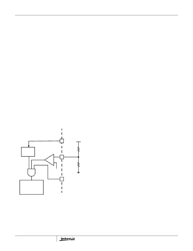
�2� -� The� ISL6561� features� an� enable� input� (EN)� for� power�
�sequencing� between� the� controller� bias� voltage� and� another�
�voltage� rail.� The� enable� comparator� holds� the� ISL6561� in�
�shutdown� until� the� voltage� at� EN� rises� above� 1.24V.� The�
�enable� comparator� has� about� 100mV� of� hysteresis� to�
�prevent� bounce.� It� is� important� that� the� driver� ICs� reach� their�
�POR� level� before� the� ISL6561� becomes� enabled.� The�
�schematic� in� Figure� 9� demonstrates� sequencing� the� ISL6561�
�with� the� HIP660X� family� of� Intersil� MOSFET� drivers,� which�
�require� 12V� bias.�
�3� -� The� voltage� on� ENLL� must� be� logic� high� to� enable� the�
�controller.� This� pin� is� typically� connected� to� the�
�VID_PGOOD.�
�4� -� The� VID� code� must� not� be� 111111� or� 111110.� These�
�codes� signal� the� controller� that� no� load� is� present.� The�
�controller� will� enter� shut-down� mode� after� receiving� either� of�
�these� codes� and� will� execute� soft� start� upon� receiving� any�
�other� code.� These� codes� can� be� used� to� enable� or� disable�
�the� controller� but� it� is� not� recommended.� After� receiving� one�
�of� these� codes,� the� controller� executes� a� 2-cycle� delay�
�ISL6561� INTERNAL� CIRCUIT�
�EXTERNAL� CIRCUIT�
�before� changing� the� overvoltage� trip� level� to� the� shut-down�
�level� and� disabling� PWM.� Overvoltage� shutdown� cannot� be�
�reset� using� one� of� these� codes.�
�VCC�
�+� 12� V�
�To� enable� the� controller,� VCC� must� be� greater� than� the� POR�
�threshold;� the� voltage� on� EN� must� be� greater� than� 1.24V;� for�
�POR�
�CIRCUIT�
�ENABLE�
�COMPARATOR�
�+�
�-�
�EN�
�10.7k� ?�
�1.40k� ?�
�ISL6561CR,� ENLL� must� be� logic� high;� and� VID� cannot� be�
�equal� to� 111111� or� 111110.� When� each� of� these� conditions�
�is� true,� the� controller� immediately� begins� the� soft-start�
�sequence.�
�Soft-Start�
�1.24V�
�ENLL�
�SOFT� START�
�AND�
�FAULT� LOGIC�
�FIGURE� 9.� POWER� SEQUENCING� USING� THRESHOLD-�
�SENSITIVE� ENABLE� (EN)� FUNCTION�
�During� soft� start,� the� DAC� voltage� ramps� linearly� from� zero� to�
�the� programmed� VID� level� as� shown� in� Figure� 10.� The� PWM�
�signals� remain� in� the� high-impedance� state� until� the�
�controller� detects� that� the� ramping� DAC� level� has� reached�
�the� output-voltage� level.� This� protects� the� system� against� the�
�large,� negative� inductor� currents� that� would� otherwise� occur�
�when� starting� with� a� pre-existing� charge� on� the� output� as� the�
�controller� attempted� to� regulate� to� zero� volts� at� the� beginning�
�of� the� soft-start� cycle.� The� soft-start� time,� t� SS� ,� begins� with� a�
�delay� period� equal� to� 64� switching� cycles� followed� by� a� linear�
�ramp� with� a� rate� determined� by� the� switching� period,� 1/f� SW� .�
�t� SS� =� -----------------------------------------�
�17�
�64� +� 1280� ?� VID�
�f� SW�
�(EQ.� 14)�
�FN9098.5�
�May� 12,� 2005�
�相关PDF资料 |
PDF描述 |
|---|---|
| ISL6563IR-T | IC CTRLR PWM MULTIPHASE 24-QFN |
| ISL6564AIRZ | IC REG CTRLR BUCK PWM VM 40-QFN |
| ISL6564IR-T | IC REG CTRLR BUCK PWM VM 40-QFN |
| ISL6565BCV-T | IC REG CTRLR BUCK PWM VM 28TSSOP |
| ISL6566AIRZ | IC CTRLR PWM 3PHASE BUCK 40-QFN |
相关代理商/技术参数 |
参数描述 |
|---|---|
| ISL6561CRZ | 功能描述:IC CTRLR PWM MULTIPHASE 40-QFN RoHS:是 类别:集成电路 (IC) >> PMIC - 稳压器 - 专用型 系列:- 标准包装:43 系列:- 应用:控制器,Intel VR11 输入电压:5 V ~ 12 V 输出数:1 输出电压:0.5 V ~ 1.6 V 工作温度:-40°C ~ 85°C 安装类型:表面贴装 封装/外壳:48-VFQFN 裸露焊盘 供应商设备封装:48-QFN(7x7) 包装:管件 |
| ISL6561CRZ | 制造商:Intersil Corporation 功能描述:Pulse Width Modulation (PWM) Controller |
| ISL6561CRZA | 功能描述:IC CTRLR PWM MULTIPHASE 40-QFN RoHS:是 类别:集成电路 (IC) >> PMIC - 稳压器 - 专用型 系列:- 标准包装:43 系列:- 应用:控制器,Intel VR11 输入电压:5 V ~ 12 V 输出数:1 输出电压:0.5 V ~ 1.6 V 工作温度:-40°C ~ 85°C 安装类型:表面贴装 封装/外壳:48-VFQFN 裸露焊盘 供应商设备封装:48-QFN(7x7) 包装:管件 |
| ISL6561CRZA-T | 功能描述:IC CTRLR PWM MULTIPHASE 40-QFN RoHS:是 类别:集成电路 (IC) >> PMIC - 稳压器 - 专用型 系列:- 标准包装:43 系列:- 应用:控制器,Intel VR11 输入电压:5 V ~ 12 V 输出数:1 输出电压:0.5 V ~ 1.6 V 工作温度:-40°C ~ 85°C 安装类型:表面贴装 封装/外壳:48-VFQFN 裸露焊盘 供应商设备封装:48-QFN(7x7) 包装:管件 |
| ISL6561CRZR5208 | 制造商:Rochester Electronics LLC 功能描述: 制造商:Intersil Corporation 功能描述: |
发布紧急采购,3分钟左右您将得到回复。