- 您现在的位置:买卖IC网 > PDF目录15181 > ISL6567IRZ-TS2698 (Intersil)IC REG CTRLR BUCK PWM VM 24-QFN PDF资料下载
参数资料
| 型号: | ISL6567IRZ-TS2698 |
| 厂商: | Intersil |
| 文件页数: | 24/25页 |
| 文件大小: | 0K |
| 描述: | IC REG CTRLR BUCK PWM VM 24-QFN |
| 标准包装: | 6,000 |
| PWM 型: | 电压模式 |
| 输出数: | 1 |
| 频率 - 最大: | 1.5MHz |
| 占空比: | 66% |
| 电源电压: | 4.9 V ~ 5.5 V |
| 降压: | 是 |
| 升压: | 无 |
| 回扫: | 无 |
| 反相: | 无 |
| 倍增器: | 无 |
| 除法器: | 无 |
| Cuk: | 无 |
| 隔离: | 无 |
| 工作温度: | -40°C ~ 85°C |
| 封装/外壳: | 24-VFQFN 裸露焊盘 |
| 包装: | 带卷 (TR) |
�� �
�
�ISL6567�
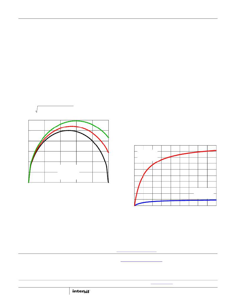
�Find� the� intersection� of� the� active� channel� curve� and� duty� cycle�
�for� your� particular� application.� The� resulting� ripple� current�
�multiplier� from� the� y-axis� is� then� multiplied� by� the�
�normalization� factor,� K� NORM� ,� to� determine� the� total� output�
�ripple� current� for� the� given� application.�
�Use� a� mix� of� input� bypass� capacitors� to� control� the� input�
�voltage� ripple.� Use� ceramic� capacitance� for� the� high�
�frequency� decoupling� and� bulk� capacitors� to� supply� the� RMS�
�current.� Minimize� the� connection� path� inductance� of� the� high�
�frequency� decoupling� ceramic� capacitors� (from� drain� of�
�Δ� I� TOTAL� =� K� NORM� ?� K� CM�
�(EQ.� 33)�
�upper� MOSFET� to� source� of� lower� MOSFET).�
�For� bulk� capacitance,� several� electrolytic� or� high-capacity� MLC�
�INPUT� CAPACITOR� SELECTION�
�The� important� parameters� for� the� bulk� input� capacitors� are�
�the� voltage� rating� and� the� RMS� current� rating.� For� reliable�
�operation,� select� bulk� input� capacitors� with� voltage� and�
�current� ratings� above� the� maximum� input� voltage� and� largest�
�RMS� current� required� by� the� circuit.� The� capacitor� voltage�
�rating� should� be� at� least� 1.25� times� greater� than� the�
�maximum� input� voltage.� The� input� RMS� current� required� for� a�
�multi-phase� converter� can� be� approximated� with� the� aid� of�
�Figure� 28.� For� a� more� exact� calculation� of� the� input� RMS�
�current� use� Equation� 34.�
�capacitors� may� be� needed.� For� surface� mount� designs,� solid�
�tantalum� capacitors� can� be� used,� but� caution� must� be� exercised�
�with� regard� to� the� capacitor� surge� current� rating.� These� capacitors�
�must� be� capable� of� handling� the� surge-current� at� power-up.�
�APPLICATION� SYSTEM� DC� TOLERANCE�
�Although� the� ISL6567� features� a� tight� voltage� reference,� the�
�overall� system� DC� tolerance� can� be� affected� by� the� tolerance�
�of� the� other� components� employed.� The� resistive� divider� used�
�to� set� the� output� voltage� will� directly� influence� the� system� DC�
�voltage� tolerance.� Figure� 29� details� the� absolute� worst� case�
�tolerance� stack-up� for� 1%� and� 0.1%� feedback� resistors,� and�
�I� O� ?� (� D� –� D� )� +� I� L� ,� PP� ?� -------�
�REF� TM� ?� ---------------------------------------------------------� –� 1�
�k� ?� R� PTM�
�TOL� =� ------------------------------------------------------------------------------------------� [%]�
�I� IN� (� RMS� )� =�
�0.3�
�0.2�
�2� 2� 2� D�
�12�
�(EQ.� 34)�
�assuming� the� ISL6567� is� regulating� at� 0.8%� above� its� nominal�
�reference.� Other� component� tolerance� stack-ups� may� be�
�investigated� using� the� following� equation,� where� REF� TM� ,� R� PTM� ,�
�and� R� STM� are� the� tolerance� multipliers� corresponding� to� V� REF� ,�
�R� S� ,� and� R� P� ,� respectively.�
�(� k� –� 1� )� ?� R� STM� +� R� PTM�
�(EQ.� 35)�
�100�
�2.8�
�2.6�
�R� STM� =� 1.01�
�0.1�
�I� L,PP� =� 0�
�I� L,PP� =� 0.5� x� I� O�
�I� L,PP� =� 0.75� x� I� O�
�2.4�
�2.2�
�2.0�
�1.8�
�R� PTM� =� 0.99�
�REF� TM� =� 1.008�
�0�
�0�
�0.1�
�0.2�
�0.3�
�0.4�
�0.5�
�1.6�
�DUTY� CYCLE� (V� O� /V� IN� )�
�FIGURE� 28.� NORMALIZED� INPUT� RMS� CURRENT� vs� DUTY� CYCLE�
�FOR� A� 2-PHASE� CONVERTER�
�1.4�
�1.2�
�1.0�
�R� STM� =� 1.001�
�R� PTM� =� 0.999�
�REF� TM� =� 1.008�
�As� the� input� capacitors� are� responsible� for� sourcing� the� AC�
�component� of� the� input� current� flowing� into� the� upper�
�MOSFETs,� their� RMS� current� capacity� must� be� sufficient� to�
�0.8�
�1�
�2�
�3�
�4�
�5� 6�
�k� =� V� OUT� /V� REF�
�7�
�8�
�9�
�10�
�handle� the� AC� component� of� the� current� drawn� by� the� upper�
�MOSFETs.� Figure� 28� can� be� used� to� determine� the�
�input-capacitor� RMS� current� function� of� duty� cycle,� maximum�
�FIGURE� 29.� WORST� CASE� SYSTEM� DC� REGULATION� TOLERANCE�
�(V� REF� AT� 0.8%� ABOVE� NOMINAL)�
�sustained� output� current� (I� O� ),� and� the� ratio� of� the� peak-to-peak�
�inductor� current� (I� L,PP� )� to� the� maximum� sustained� load�
�current,� I� O� .�
��Intersil� products� are� manufactured,� assembled� and� tested� utilizing� ISO9000� quality� systems� as� noted�
�in� the� quality� certifications� found� at� www.intersil.com/design/quality�
�Intersil� products� are� sold� by� description� only.� Intersil� Corporation� reserves� the� right� to� make� changes� in� circuit� design,� software� and/or� specifications� at� any� time�
�without� notice.� Accordingly,� the� reader� is� cautioned� to� verify� that� data� sheets� are� current� before� placing� orders.� Information� furnished� by� Intersil� is� believed� to� be�
�accurate� and� reliable.� However,� no� responsibility� is� assumed� by� Intersil� or� its� subsidiaries� for� its� use;� nor� for� any� infringements� of� patents� or� other� rights� of� third�
�parties� which� may� result� from� its� use.� No� license� is� granted� by� implication� or� otherwise� under� any� patent� or� patent� rights� of� Intersil� or� its� subsidiaries.�
�For� information� regarding� Intersil� Corporation� and� its� products,� see� www.intersil.com�
�24�
�FN9243.4�
�August� 9,� 2011�
�相关PDF资料 |
PDF描述 |
|---|---|
| ISL6567IRZ-T | IC REG CTRLR BUCK PWM VM 24-QFN |
| B41041A6158M | 1500UF 50V 16X35.5 SINGLE END |
| ISL6522IVZ | IC REG CTRLR BST PWM VM 14-TSSOP |
| ASC15DRTN | CONN EDGECARD 30POS .100 DIP SLD |
| H2ABT-10110-S4-ND | JUMPER-H1502TR/A2015S/H1500TR10" |
相关代理商/技术参数 |
参数描述 |
|---|---|
| ISL6568CR | 功能描述:IC CTRLR PWM BUCK 2PHASE 32-QFN RoHS:否 类别:集成电路 (IC) >> PMIC - 稳压器 - 专用型 系列:- 产品培训模块:Lead (SnPb) Finish for COTS Obsolescence Mitigation Program 标准包装:2,000 系列:- 应用:电源,ICERA E400,E450 输入电压:4.1 V ~ 5.5 V 输出数:10 输出电压:可编程 工作温度:-40°C ~ 85°C 安装类型:表面贴装 封装/外壳:42-WFBGA,WLCSP 供应商设备封装:42-WLP 包装:带卷 (TR) |
| ISL6568CR-T | 功能描述:IC CTRLR PWM BUCK 2PHASE 32-QFN RoHS:否 类别:集成电路 (IC) >> PMIC - 稳压器 - 专用型 系列:- 产品培训模块:Lead (SnPb) Finish for COTS Obsolescence Mitigation Program 标准包装:2,000 系列:- 应用:电源,ICERA E400,E450 输入电压:4.1 V ~ 5.5 V 输出数:10 输出电压:可编程 工作温度:-40°C ~ 85°C 安装类型:表面贴装 封装/外壳:42-WFBGA,WLCSP 供应商设备封装:42-WLP 包装:带卷 (TR) |
| ISL6568CRZ | 制造商:Intersil Corporation 功能描述:CURRENT MODE PWM CNTRLR 0.8375V TO 12V 60A 32QFN EP - Rail/Tube 制造商:Intersil 功能描述:2-PH PWM CNTRLR VRM9 W/2-DRVRS 10 K8 DAC |
| ISL6568CRZA | 制造商:Intersil Corporation 功能描述:CURRENT MODE PWM CNTRLR 0.8375V TO 12V 60A 32QFN EP - Rail/Tube 制造商:Intersil 功能描述:W/ANNEAL 2-PH PWM CNTRLR 2-DRVRS VRM9 |
| ISL6568CRZA-T | 制造商:Intersil Corporation 功能描述:CURRENT MODE PWM CNTRLR 0.8375V TO 12V 60A 32QFN EP - Tape and Reel 制造商:Intersil 功能描述:W/ANNEAL 2-PHS PWM CNTRLR W/2-DRVRS |
发布紧急采购,3分钟左右您将得到回复。