参数资料
| 型号: | ISL6569CR-T |
| 厂商: | Intersil |
| 文件页数: | 18/22页 |
| 文件大小: | 0K |
| 描述: | IC REG CTRLR DIVIDER PWM 32-QFN |
| 标准包装: | 6,000 |
| PWM 型: | 控制器 |
| 输出数: | 1 |
| 频率 - 最大: | 2MHz |
| 占空比: | 75% |
| 电源电压: | 4.75 V ~ 5.25 V |
| 降压: | 是 |
| 升压: | 无 |
| 回扫: | 无 |
| 反相: | 无 |
| 倍增器: | 无 |
| 除法器: | 是 |
| Cuk: | 无 |
| 隔离: | 无 |
| 工作温度: | 0°C ~ 70°C |
| 封装/外壳: | 32-VFQFN 裸露焊盘 |
| 包装: | 带卷 (TR) |
�� �
�
�ISL6569�
�less� than� 50%.� Nevertheless,� both� inequalities� should� be�
�evaluated,� and� L� should� be� selected� based� on� the� lower� of�
�the� two� results.� In� each� equation,� L� is� the� per-channel�
�each� of� the� three� cases� which� follow,� there� is� a� separate� set�
�of� equations� for� the� compensation� components.�
�-------------------� >� f� 0�
�R� C� =� R� FB� ------------------------------------�
�2� π� V� PP� R� FB� f� 0�
�-------------------� ≤� f� 0� <� ------------------------------�
�inductance,� and� C� is� the� total� output� capacitance.�
�Compensation�
�The� two� opposing� goals� of� compensating� the� voltage�
�regulator� are� stability� and� speed.� Depending� on� whether� the�
�regulator� employs� the� optional� load-line� regulation� as�
�described� in� Load-Line� Regulation� ,� there� are� two� distinct�
�methods� for� achieving� these� goals.�
�COMPENSATING� LOAD-LINE� REGULATED�
�CONVERTER�
�Case� 1:�
�Case� 2:�
�1�
�2� π� LC�
�2� π� f� 0� V� pp� LC�
�0.75V� IN�
�0.75V� IN�
�C� C� =� ------------------------------------�
�1� 1�
�2� π� LC� 2� π� C� (� ESR� )�
�R� C� =� R� FB� --------------------------------------------�
�0.75� V�
�C� C� =� -------------------------------------------------------------�
�PP� R� FB� LC�
�(� 2� π� )� 2� f� 2� V�
�The� load-line� regulated� converter� behaves� in� a� similar�
�manner� to� a� peak-current� mode� controller� because� the� two�
�poles� at� the� output-filter� L-C� resonant� frequency� split� with�
�the� introduction� of� current� information� into� the� control� loop.�
�The� final� location� of� these� poles� is� determined� by� the� system�
�function,� the� gain� of� the� current� signal,� and� the� value� of� the�
�V� PP� (� 2� π� )� 2� f� 02� LC�
�IN�
�0.75V� IN�
�0�
�(EQ.� 27)�
�f� 0� >� ------------------------------�
�0.75� V� IN� (� ESR� )�
�compensation� components,� R� C� and� C� C� .�
�Since� the� system� poles� and� zero� are� effected� by� the� values�
�of� the� components� that� are� meant� to� compensate� them,� the�
�solution� to� the� system� equation� becomes� fairly� complicated.�
�Case� 3:�
�1�
�2� π� C� (� ESR� )�
�2� π� f� 0� V� pp� L�
�R� C� =� R� FB� ------------------------------------------�
�2� π� V� PP� R� FB� f� 0� L�
�Fortunately� there� is� a� simple� approximation� that� comes� very�
�close� to� an� optimal� solution.� Treating� the� system� as� though� it�
�were� a� voltage-mode� regulator� by� compensating� the� L-C�
�poles� and� the� ESR� zero� of� the� voltage-mode� approximation�
�yields� a� solution� that� is� always� stable� with� very� close� to� ideal�
�transient� performance.�
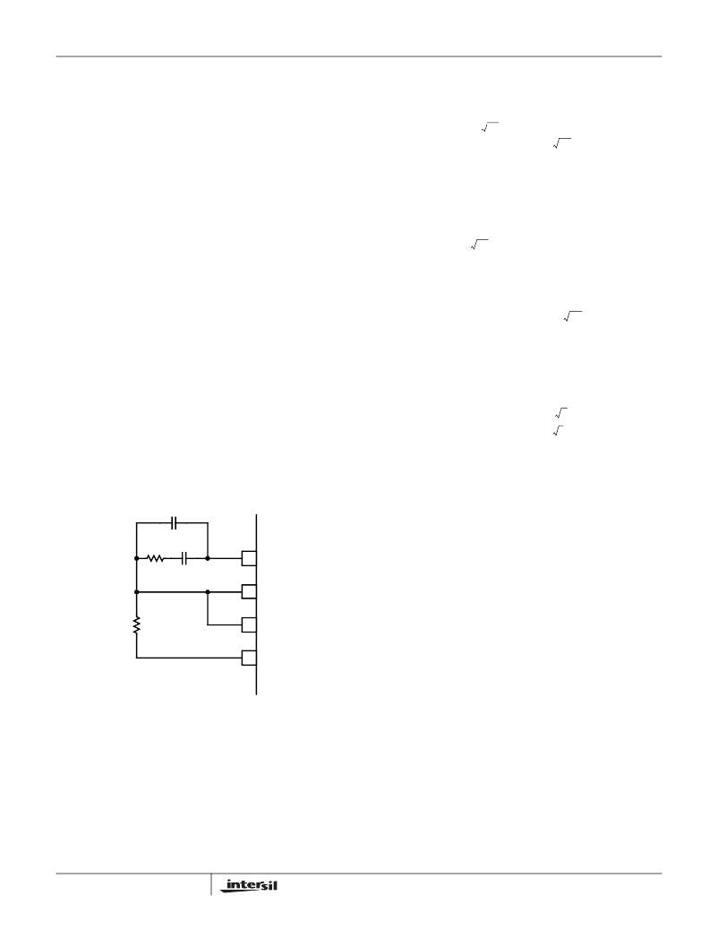
�C� 2� (OPTIONAL)�
�0.75V� IN� (� ESR� )� C�
�C� C� =� -------------------------------------------------�
�In� Equations� 27,� L� is� the� per-channel� filter� inductance�
�divided� by� 2� (the� number� of� active� channels);� C� is� the� sum�
�total� of� all� output� capacitors;� ESR� is� the� equivalent-series�
�resistance� of� the� bulk� output-filter� capacitance;� and� V� PP� is�
�the� peak-to-peak� sawtooth� signal� amplitude� as� described� in�
�Figure� 5� and� Electrical� Specifications� .�
�R� C�
�C� C�
�COMP�
�Once� selected,� the� compensation� values� in� Equations� 27�
�assure� a� stable� converter� with� reasonable� transient� perfor-�
�R� FB�
�+�
�V� DROOP�
�-�
�FB�
�IOUT�
�VDIFF�
�mance.� In� most� cases,� transient� performance� can� be�
�improved� by� making� adjustments� to� R� C� .� Slowly� increase� the�
�value� of� R� C� while� observing� the� transient� performance� on� an�
�oscilloscope� until� no� further� improvement� is� noted.� Normally,�
�C� C� will� not� need� adjustment.� Keep� the� value� of� C� C� from�
�Equations� 27� unless� some� performance� issue� is� noted.�
�The� optional� capacitor� C� 2� ,� is� sometimes� needed� to� bypass�
�noise� away� from� the� PWM� comparator� (see� Figure� 13).� Keep�
�a� position� available� for� C� 2� ,� and� be� prepared� to� install� a� high-�
�FIGURE� 13.� COMPENSATION� CONFIGURATION� FOR�
�LOAD-LINE� REGULATED� ISL6569� CIRCUIT�
�The� feedback� resistor,� R� FB� ,� has� already� been� chosen� as�
�outlined� in� Load-Line� Regulation� Resistor� .� Select� a� target�
�bandwidth� for� the� compensated� system,� f� 0� .� The� target�
�bandwidth� must� be� large� enough� to� assure� adequate�
�transient� performance,� but� smaller� than� 1/3� of� the� per-�
�channel� switching� frequency.� The� values� of� the�
�compensation� components� depend� on� the� relationships� of� f� 0�
�to� the� L-C� pole� frequency� and� the� ESR� zero� frequency.� For�
�18�
�frequency� capacitor� of� between� 22pF� and� 150pF� in� case� any�
�trailing� edge� jitter� problem� is� noted.�
�Compensation� without� load-line� regulation�
�The� non� load-line� regulated� converter� is� accurately� modeled�
�as� a� voltage-mode� regulator� with� two� poles� at� the� L-C�
�resonant� frequency� and� a� zero� at� the� ESR� frequency.� A� type-�
�III� controller,� as� shown� in� Figure� 14,� provides� the� necessary�
�compensation.�
�FN9085.7�
�December� 29,� 2004�
�相关PDF资料 |
PDF描述 |
|---|---|
| ISL6571CRZ | IC MOSF DRVR/SYNC SW COMPL 68QFN |
| ISL6611AIRZ | IC REG CTRLR DOUBLER PWM 16-QFN |
| ISL6617IRZ | IC PWM DOUBLER MONITOR 10DFN |
| ISL6627IRZ-T | IC CONTROLLER VR11.1 VR12 10DFN |
| ISL6719ARZ-T | IC REG LDO ADJ .1A 9-DFN |
相关代理商/技术参数 |
参数描述 |
|---|---|
| ISL6569CRZ | 功能描述:IC REG CTRLR DIVIDER PWM 32-QFN RoHS:是 类别:集成电路 (IC) >> PMIC - 稳压器 - DC DC 切换控制器 系列:- 产品培训模块:Lead (SnPb) Finish for COTS Obsolescence Mitigation Program 标准包装:2,500 系列:- PWM 型:电流模式 输出数:1 频率 - 最大:275kHz 占空比:50% 电源电压:18 V ~ 110 V 降压:无 升压:无 回扫:无 反相:无 倍增器:无 除法器:无 Cuk:无 隔离:是 工作温度:-40°C ~ 85°C 封装/外壳:8-SOIC(0.154",3.90mm 宽) 包装:带卷 (TR) |
| ISL6569CRZ-T | 功能描述:IC REG CTRLR DIVIDER PWM 32-QFN RoHS:是 类别:集成电路 (IC) >> PMIC - 稳压器 - DC DC 切换控制器 系列:- 产品培训模块:Lead (SnPb) Finish for COTS Obsolescence Mitigation Program 标准包装:2,500 系列:- PWM 型:电流模式 输出数:1 频率 - 最大:275kHz 占空比:50% 电源电压:18 V ~ 110 V 降压:无 升压:无 回扫:无 反相:无 倍增器:无 除法器:无 Cuk:无 隔离:是 工作温度:-40°C ~ 85°C 封装/外壳:8-SOIC(0.154",3.90mm 宽) 包装:带卷 (TR) |
| ISL6571CR | 制造商:Rochester Electronics LLC 功能描述:- Bulk 制造商:Intersil Corporation 功能描述: |
| ISL6571CR-T | 制造商:Rochester Electronics LLC 功能描述:- Bulk |
| ISL6571CRZ | 功能描述:IC MOSF DRVR/SYNC SW COMPL 68QFN RoHS:是 类别:集成电路 (IC) >> PMIC - MOSFET,电桥驱动器 - 内部开关 系列:- 标准包装:1,000 系列:- 类型:高端/低端驱动器 输入类型:SPI 输出数:8 导通状态电阻:850 毫欧,1.6 欧姆 电流 - 输出 / 通道:205mA,410mA 电流 - 峰值输出:500mA,1A 电源电压:9 V ~ 16 V 工作温度:-40°C ~ 150°C 安装类型:表面贴装 封装/外壳:20-SOIC(0.295",7.50mm 宽) 供应商设备封装:PG-DSO-20-45 包装:带卷 (TR) |
发布紧急采购,3分钟左右您将得到回复。