- 您现在的位置:买卖IC网 > Datasheet目录625 > LD4006P0 (Red Lion Controls)COUNTER 6 DIGIT DUAL 4.0" RED Datasheet资料下载
参数资料
| 型号: | LD4006P0 |
| 厂商: | Red Lion Controls |
| 文件页数: | 14/16页 |
| 文件大小: | 0K |
| 描述: | COUNTER 6 DIGIT DUAL 4.0" RED |
| 标准包装: | 1 |
| 系列: | LD |
| 计数速率: | 35kHz |
| 数字/字母数: | 6 |
| 输入类型: | 电压、开关外壳、晶体管开关 |
| 输出类型: | 继电器和 RS232/RS485 |
| 电源电压: | 11 V ~ 16 VDC,85 V ~ 250 VAC |
| 显示器类型: | LED 红 |
�� �
�
�set� to� 9600� baud.� This� is� the� factory� default� setting,� so� a� new� meter� should�
�arrive� ready� for� copying.� The� meter� sending� the� program� settings� (master)�
�should� be� set� to� the� desired� baud� rate� for� the� application� (if� different� than�
�9600).� This� baud� rate� setting� will� then� be� copied� to� the� receiver(s).�
�Copy� Connections� :�
�To� connect� the� LD� meters� for� copying,� refer� to� section� 3.5� Serial� Wiring� for�
�details.� The� meter� shown� in� the� figures� as� LD� METER� will� be� the� master.�
�1.� RS232� -� Allows� copying� from� the� master� meter� to� a� single� receiver� only.�
�2.� RS485� -� Allows� copying� from� the� master� meter� to� one� or� more� receivers�
�simultaneously.� Up� to� 31� receiving� meters� can� be� connected� during� copying.�
�Sending� Serial� Commands� and� Data�
�When� sending� commands� to� the� meter,� a� string� containing� at� least� one�
�Copy� Procedure� :�
�1.� Connect� the� master� and� receiver(s)� using� RS232� or� RS485� terminals.�
�2.� Apply� power� to� the� meters.� The� receiving� meter(s)� must� be� operating� in� the�
�normal� display� mode� (not� programming� mode).�
�3.� On� the� master� meter,� proceed� to� the� Copy� Program� Settings� parameter� and�
�select� ???� to� begin� copying.�
�4.� During� the� copy� process� (~� 2� sec.),� the� master� meter� displays� an� upload� message�
�(� ?????� )� while� the� receiver(s)� displays� a� download� message� (� ?????� ).� This�
�indicates� successful� communication� between� the� master� and� receiver(s).�
�5.� When� copying� is� completed,� all� receivers� display� the� power-up� sequence� and�
�return� to� normal� operating� mode,� programmed� with� all� the� same� settings� as�
�the� master� meter.� The� master� remains� at� the� ????� prompt,� ready� for� another�
�receiver(s)� to� be� connected� for� copying.�
�Register� Identification� Chart�
�command� character� must� be� constructed.� A� command� string� consists� of� a�
�command� character,� a� value� identifier,� numerical� data� (if� writing� data� to� the�
�meter)� followed� by� a� command� terminator� character,� *� or� $.�
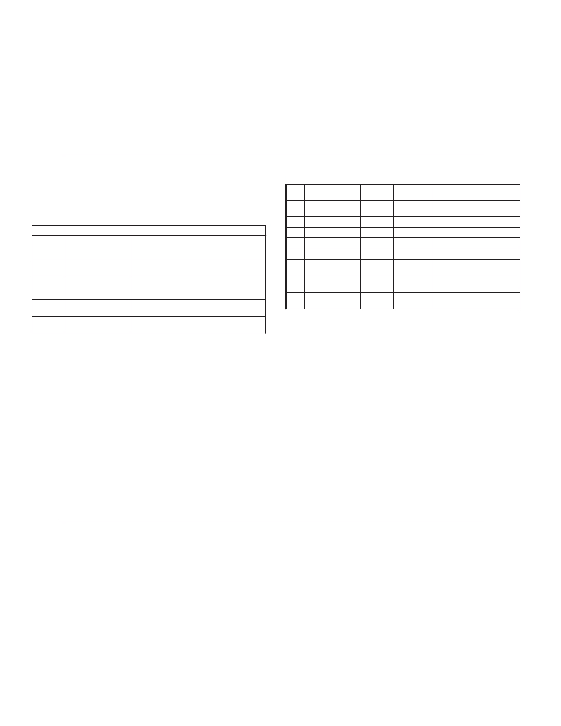
�Command� Chart�
�ID�
�A�
�B�
�Value� Description�
�Counter� A�
�Counter� B�
�MNEMONIC�
�CTA�
�CTB�
�Applicable�
�Commands�
�T,� V,� R�
�T,� V,� R�
�Transmit� Details� (T� and� V)�
�6� digit� positive/5� digit�
�negative� (with� minus� sign)�
�5� digit,� positive� only�
�Command� Description�
�Notes�
�C�
�Rate�
�RTE�
�T�
�5� digit,� positive� only�
�N�
�T�
�Node� (meter)�
�Address� Specifier�
�Transmit� Value� (read)�
�Address� a� specific� meter.� Must� be� followed�
�by� one� or� two� digit� node� address.� Not�
�required� when� node� address� =� 0.�
�Read� a� register� from� the� meter.� Must� be�
�followed� by� a� register� ID� character.�
�D�
�E�
�F�
�Scale� Factor� A�
�Scale� Factor� B�
�Setpoint� 1�
�(Reset� Output� 1)�
�SFA�
�SFB�
�SP1�
�T,� V�
�T,� V�
�T,� V,� R�
�6� digit,� positive� only�
�6� digit,� positive� only�
�per� setpoint� Assignment,�
�same� as� Counter� or� Rate�
�V�
�Write� to� register� of� the� meter.� Must� be�
�Value� Change� (write)� followed� by� a� register� ID� character� and�
�G�
�Setpoint� 2�
�(Reset� Output� 2)�
�SP2�
�T,� V,� R�
�per� setpoint� Assignment,�
�same� as� Counter� or� Rate�
�R�
�Reset�
�numeric� data.�
�Reset� a� count� value� or� setpoint� output.� Must�
�be� followed� by� a� register� ID� character�
�H�
�Counter� A� Count�
�Load� Value�
�CLD�
�T,� V,� R�
�6� digit� positive/5� digit�
�negative� (with� minus� sign)�
�P�
�Block� Print� Request�
�(read)�
�Initiates� a� block� print� output.� Registers� in� the�
�print� block� are� selected� in� Print� Options.�
�Command� String� Examples:�
�1.� Node� address� =� 17,� Write� 350� to� the� Setpoint� 1� value�
�Command� String� Construction�
�The� command� string� must� be� constructed� in� a� specific� sequence.� The� meter�
�does� not� respond� with� an� error� message� to� illegal� commands.� The� following�
�procedure� details� construction� of� a� command� string:�
�1.� The� first� 2� or� 3� characters� consist� of� the� Node� Address� Specifier� (N)� followed�
�by� a� 1� or� 2� character� node� address� number.� The� node� address� number� of� the�
�meter� is� programmable.� If� the� node� address� is� 0,� this� command� and� the� node�
�address� itself� may� be� omitted.� This� is� the� only� command� that� may� be� used� in�
�conjunction� with� other� commands.�
�2.� After� the� optional� address� specifier,� the� next� character� is� the� command�
�character.�
�3.� The� next� character� is� the� register� ID.� This� identifies� the� register� that� the�
�command� affects.� The� P� command� does� not� require� a� register� ID� character.� It�
�prints� all� the� active� selections� chosen� in� the� Print� Options� menu� parameter.�
�4.� If� constructing� a� value� change� command� (writing� data),� the� numeric� data� is�
�sent� next.�
�5.� All� command� strings� must� be� terminated� with� the� string� termination�
�characters� *� or� $.� The� meter� does� not� begin� processing� the� command� string�
�until� this� character� is� received.� See� timing� diagram� figure� for� differences� in�
�meter� response� time� when� using� the� *� and� $� terminating� characters.�
�Receiving� Data� From� The� Meter�
�Data� is� transmitted� from� the� meter� in� response� to� either� a� transmit� command�
�(T),� a� block� print� request� command� (P)� or� a� User� Input� print� request.� The�
�response� from� the� meter� is� either� a� full� field� transmission� or� an� abbreviated�
�transmission,� depending� on� the� selection� chosen� in� Module� 5.�
�Full� Field� Transmission�
�String:� N17VF350*�
�2.� Node� address� =� 5,� Read� Counter� A,� response� time� of� 50� msec� min�
�String:� N5TA*�
�3.� Node� address� =� 0,� Reset� Setpoint� 1� output�
�String:� RF*�
�4.� Node� address� =� 31,� Request� a� Block� Print� Output,� response� time� of� 2� msec� min�
�String:� N31P$�
�Transmitting� Data� to� the� Meter�
�Numeric� data� sent� to� the� meter� must� be� limited� to� transmit� details� listed� in� the�
�Register� Identification� Chart.� Leading� zeros� are� ignored.� Negative� numbers�
�must� have� a� minus� sign.� The� meter� ignores� any� decimal� point� and� conforms� the�
�number� to� the� scaled� resolution.� (For� example:� The� meter� ’s� scaled� decimal� point�
�position� is� set� for� 0.0� and� 25� is� written� to� a� register.� The� value� of� the� register� is�
�now� 2.5.� In� this� case,� write� a� value� of� 250� to� equal� 25.0).�
�Note:� Since� the� meter� does� not� issue� a� reply� to� value� change� commands,� follow�
�with� a� transmit� value� command� for� readback� verification.�
�The� first� two� characters� transmitted� are� the� meter� address.� If� the� address�
�assigned� is� 0,� two� spaces� are� substituted.� A� space� follows� the� meter� address� field.�
�The� next� three� characters� are� the� register� mnemonic,� as� shown� in� the� Register�
�Identification� Chart.�
�The� numeric� data� is� transmitted� next.� The� numeric� field� (bytes� 7� to� 18)� is� 12�
�characters� long.� When� a� requested� counter� or� rate� value� exceeds� the� meter� ’s�
�Byte�
�1,� 2�
�3�
�4-6�
�7-18�
�19�
�20�
�21�
�22�
�23�
�Description�
�2� byte� Node� Address� field� [00-99]�
�<SP>� (Space)�
�3� byte� Register� Mnemonic� field�
�12� byte� data� field;� 10� for� number,� one� for� sign,� one� for� decimal� point�
�<CR>� (carriage� return)�
�<LF>� (line� feed)�
�<SP>*� (Space)�
�<CR>*� (carriage� return)�
�<LF>*� (line� feed)�
�display� limits,� an� *� (used� as� an� overflow� character)� replaces� a� space� in� byte� 7.�
�Byte� 8� is� always� a� space.�
�The� remaining� ten� positions� of� this� field� consist� of� a� minus� sign� (for� negative�
�values),� a� floating� decimal� point� (if� applicable),� and� eight� positions� for� the�
�requested� value.� The� data� within� bytes� 9� to� 18� is� right-aligned� with� leading�
�spaces� for� any� unfilled� positions.�
�The� end� of� the� response� string� is� terminated� with� a� <CR>� and� <LF>.� After� the�
�last� line� of� a� block� print,� an� extra� <SP>,� <CR>� and� <LF>� are� added� to� provide�
�separation� between� the� print� blocks.�
�*� These� characters� only� appear� in� the� last� line� of� a� block� print.�
�14�
�相关PDF资料 |
PDF描述 |
|---|---|
| LD412460 | DIODE MOD ISO DUAL 2400V 600A |
| LIRT220A | CONTROL RELAY CURRENT 220VAC |
| LNXC2000 | COUNTER DUAL PRESET 115VAC |
| LP-56-850 | XFRMR 115/230V 28V 1.7A 48VA PCB |
| LS412460 | DIODE MOD ISO SGL 2400V 600A |
相关代理商/技术参数 |
参数描述 |
|---|---|
| LD400-AC | 制造商:MRV 制造商全称:MRV 功能描述:LambdaDriver Chassis - DWDM/CWDM Platform |
| LD400-DC | 制造商:MRV 制造商全称:MRV 功能描述:LambdaDriver Chassis - DWDM/CWDM Platform |
| LD400L-2AC | 制造商:MRV 制造商全称:MRV 功能描述:LambdaDriver Chassis - DWDM/CWDM Platform |
| LD400L-2DC | 制造商:MRV 制造商全称:MRV 功能描述:LambdaDriver Chassis - DWDM/CWDM Platform |
| LD400L-AC | 制造商:MRV 制造商全称:MRV 功能描述:LambdaDriver Chassis - DWDM/CWDM Platform |
发布紧急采购,3分钟左右您将得到回复。