- 您现在的位置:买卖IC网 > Datasheet目录625 > LD4006P0 (Red Lion Controls)COUNTER 6 DIGIT DUAL 4.0" RED Datasheet资料下载
参数资料
| 型号: | LD4006P0 |
| 厂商: | Red Lion Controls |
| 文件页数: | 7/16页 |
| 文件大小: | 0K |
| 描述: | COUNTER 6 DIGIT DUAL 4.0" RED |
| 标准包装: | 1 |
| 系列: | LD |
| 计数速率: | 35kHz |
| 数字/字母数: | 6 |
| 输入类型: | 电压、开关外壳、晶体管开关 |
| 输出类型: | 继电器和 RS232/RS485 |
| 电源电压: | 11 V ~ 16 VDC,85 V ~ 250 VAC |
| 显示器类型: | LED 红 |
�� �
�
�??????� ?�
�MODULE MENU (PAR KEY)�
�Each� module� has� a� separate� module� menu� (which� is� shown� at� the� start� of� each�
�module� discussion).� The� PAR� key� is� pressed� to� advance� to� a� particular� parameter�
�to� be� changed,� without� changing� the� programming� of� preceding� parameters.�
�After� completing� a� module,� the� display� will� return� to� ????� ??� .� Programming�
�may� continue� by� accessing� additional� modules.�
�SELECTION� /� VALUE� ENTRY�
�For� each� parameter,� the� display� alternates� between� the� present� parameter� and�
�the� selections/value� for� that� parameter.� The� SEL� ?� and� RST� ?� keys� are� used� to�
�move� through� the� selections/values� for� that� parameter.� Pressing� the� PAR� key,�
�stores� and� activates� the� displayed� selection/value.� This� also� advances� the� meter� to�
�the� next� parameter.�
�For� numeric� values,� the� value� is� displayed� with� one� digit� flashing� (initially� the�
�right� most� digit).� Pressing� the� RST� ?� key� increments� the� digit� by� one� or� the� user�
�can� hold� the� RST� ?� key� and� the� digit� will� automatically� scroll.� The� SEL� ?� key�
�will� select� the� next� digit� to� the� left.� Pressing� the� PAR� key� will� enter� the� value� and�
�move� to� the� next� parameter.�
�PROGRAMMING� MODE� EXIT� (PAR� KEY)�
�The� Programming� Mode� is� exited� by� pressing� the� PAR� key� with� ??????� ?�
�displayed.� This� will� commit� any� stored� parameter� changes� to� memory� and� return�
�the� meter� to� the� Display� Mode.� (If� power� loss� occurs� before� returning� to� the�
�PROGRAMMING� TIPS�
�It� is� recommended� to� start� with� Module� 1� for� counting� or� Module� 2� for� rate.�
�When� programming� is� complete,� it� is� recommended� to� record� the� parameter�
�programming� and� lock� out� parameter� programming� with� the� user� input� or�
�programming� security� code.�
�FACTORY� SETTINGS�
�Factory� Settings� may� be� completely� restored� in� Module� 3.� This� is� useful� when�
�encountering� programming� problems.�
�ALTERNATING� SELECTION� DISPLAY�
�In� the� explanation� of� the� modules,� the� following� dual� display� with� arrows� will�
�appear.� This� is� used� to� illustrate� the� display� alternating� between� the� parameter�
�on� top� and� the� parameter� ’s� Factory� Setting� on� the� bottom.� In� most� cases,�
�selections� and� values� for� the� parameter� will� be� listed� on� the� right.�
�Indicates� Program� Mode� Alternating� Display�
�Parameter�
�?� ???? ??� Selection/Value�
�Factory� Settings� are� shown.�
�Display� Mode,� verify� recent� parameter� changes.)�
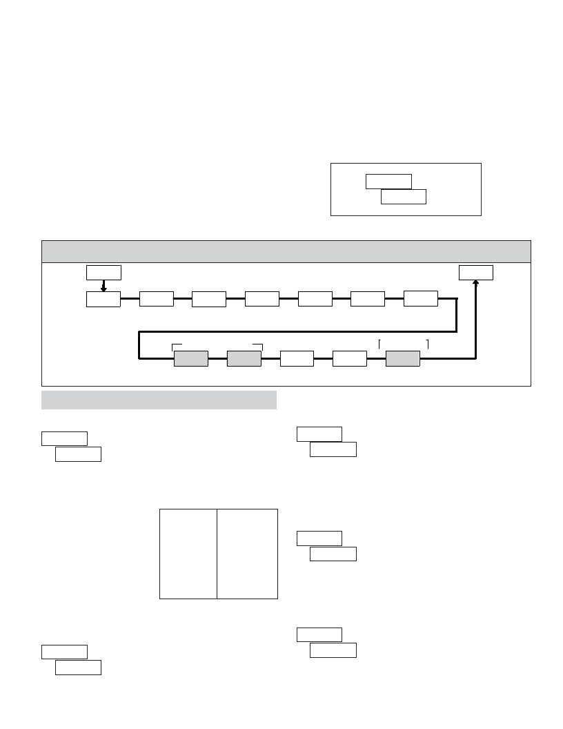
�5.1� MODULE� 1� -� I� NPUT� S� ETUP� P� ARAMETERS� (� ?????� )�
�1-INP�
�PAR�
�PARAMETER� MENU�
�Pro�
�INP� Ab�
�Count�
�Mode�
�A-dPt�
�Counter� A�
�Decimal� Point�
�A-Scf�
�Counter� A�
�Scale� Factor�
�A-rSt�
�Counter� A�
�Reset� Action�
�A-dir�
�Counter� A�
�Count� Direction�
�Cnt� Ld�
�Counter� A�
�Count� Load�
�b-bAt�
�Counter� B�
�Batch� Count�
�Dual� Count� or� Batch�
�Only�
�Value�
�Enable�
�Dual� Count� or�
�Batch� Only�
�b-dPt�
�Counter� B�
�Decimal� Point�
�b-ScF�
�Counter� B�
�Scale� Factor�
�r� P-UP�
�Counter� Reset�
�at� Power-up�
�USrINP�
�User� Input�
�Function�
�USrASN�
�User� Input�
�Assignment�
�Shaded� area� selections� only� apply� when� Counter� B� is� enabled� (Dual� Count�
�mode� or� batch� counter).�
�COUNT� MODE�
�COUNTER� A� SCALE� FACTOR�
�?� ???????�
�???? ??� ?�
�?� ????� ??�
�????� ??�
�??????�
�?????�
�?????� ?�
�?????� ?�
�?????� ?�
�??????�
�??????�
�?????� ?�
�???????� to� ???????�
�The� number� of� input� counts� is� multiplied� by� the� scale� factor� to� obtain� the�
�Select� the� count� mode� that� corresponds� with� your� application.� The� input�
�actions� are� shown� in� the� boxes� below.� For� simple� counting� applications,� it� is�
�recommended� to� use� Count� with� Direction� for� the� count� mode.� Simply� leave� the�
�direction� input� unconnected.�
�desired� process� value.� A� scale� factor� of� 1.0000� will� result� in� the� display� of� the�
�actual� number� of� input� counts.� (Details� on� scaling� calculations� are� explained� at�
�the� end� of� this� section.)*�
�DISPLAY�
�MODE�
�INPUT� A� ACTION�
�INPUT� B� ACTION�
�????� ??�
�Count� with� Direction�
�Counter� A�
�Counter� A� Direction�
�COUNTER� A� RESET� ACTION�
�??????�
�????�
�?????� ?�
�Rate/Counter�
�Dual� Counter�
�Quadrature� x1�
�Rate� only�
�Counter� A� Add�
�Count� A�
�Counter� A� Add�
�Counter� B� Add�
�Quad� A�
�?� ????�
�?????� ?�
�????�
�????� ??�
�?????� ?�
�?????� ?�
�??????�
�??????�
�Quadrature� x2�
�Quadrature� x4�
�2� Input� Add/Add�
�2� Input� Add/Subtract�
�Count� A�
�Count� A�
�Counter� A� Add�
�Counter� A� Add�
�Quad� A�
�Quad� A�
�Counter� A� Add�
�Counter� A� Subtract�
�When� Counter� A� is� reset,� it� returns� to� Zero� or� Counter� A� Count� Load� value.�
�This� reset� action� applies� to� all� Counter� A� resets,� except� a� Setpoint� generated�
�Counter� Auto� Reset� programmed� in� Module� 4.�
�Note:� The� Rate� indicator� signal� is� derived� from� Input� A� in� all� count� modes.�
�COUNTER� A� COUNT� DIRECTION�
�?????�
�COUNTER� A� DECIMAL� POINT� POSITION�
�?� ?� ????� ??????�
�?????�
�?�
�?�
�???�
�???�
�???�
�?�
�?�
�???� ?????�
�This� selects� the� decimal� point� position� for� Counter� A� and� the� setpoint� value,�
�if� assigned� to� Counter� A.� The� selection� will� also� affect� Counter� A� scale�
�factor� calculations.�
�7�
�Reverse� (� ???� )� switches� the� normal� Counter� A� count� direction� shown� in� the�
�Count� Mode� parameter� chart.�
�相关PDF资料 |
PDF描述 |
|---|---|
| LD412460 | DIODE MOD ISO DUAL 2400V 600A |
| LIRT220A | CONTROL RELAY CURRENT 220VAC |
| LNXC2000 | COUNTER DUAL PRESET 115VAC |
| LP-56-850 | XFRMR 115/230V 28V 1.7A 48VA PCB |
| LS412460 | DIODE MOD ISO SGL 2400V 600A |
相关代理商/技术参数 |
参数描述 |
|---|---|
| LD400-AC | 制造商:MRV 制造商全称:MRV 功能描述:LambdaDriver Chassis - DWDM/CWDM Platform |
| LD400-DC | 制造商:MRV 制造商全称:MRV 功能描述:LambdaDriver Chassis - DWDM/CWDM Platform |
| LD400L-2AC | 制造商:MRV 制造商全称:MRV 功能描述:LambdaDriver Chassis - DWDM/CWDM Platform |
| LD400L-2DC | 制造商:MRV 制造商全称:MRV 功能描述:LambdaDriver Chassis - DWDM/CWDM Platform |
| LD400L-AC | 制造商:MRV 制造商全称:MRV 功能描述:LambdaDriver Chassis - DWDM/CWDM Platform |
发布紧急采购,3分钟左右您将得到回复。