- 您现在的位置:买卖IC网 > PDF目录21684 > MAX17410GTM+T (Maxim Integrated)IC CTLR QPWM 2PH FOR IMV 48TQFN PDF资料下载
参数资料
| 型号: | MAX17410GTM+T |
| 厂商: | Maxim Integrated |
| 文件页数: | 16/45页 |
| 文件大小: | 0K |
| 描述: | IC CTLR QPWM 2PH FOR IMV 48TQFN |
| 产品培训模块: | Lead (SnPb) Finish for COTS Obsolescence Mitigation Program |
| 标准包装: | 2,500 |
| 系列: | * |
第1页第2页第3页第4页第5页第6页第7页第8页第9页第10页第11页第12页第13页第14页第15页当前第16页第17页第18页第19页第20页第21页第22页第23页第24页第25页第26页第27页第28页第29页第30页第31页第32页第33页第34页第35页第36页第37页第38页第39页第40页第41页第42页第43页第44页第45页
�� �
�
�Dual-Phase,� Quick-PWM� Controller�
�for� IMVP6+� CPU� Core� Power� Supplies�
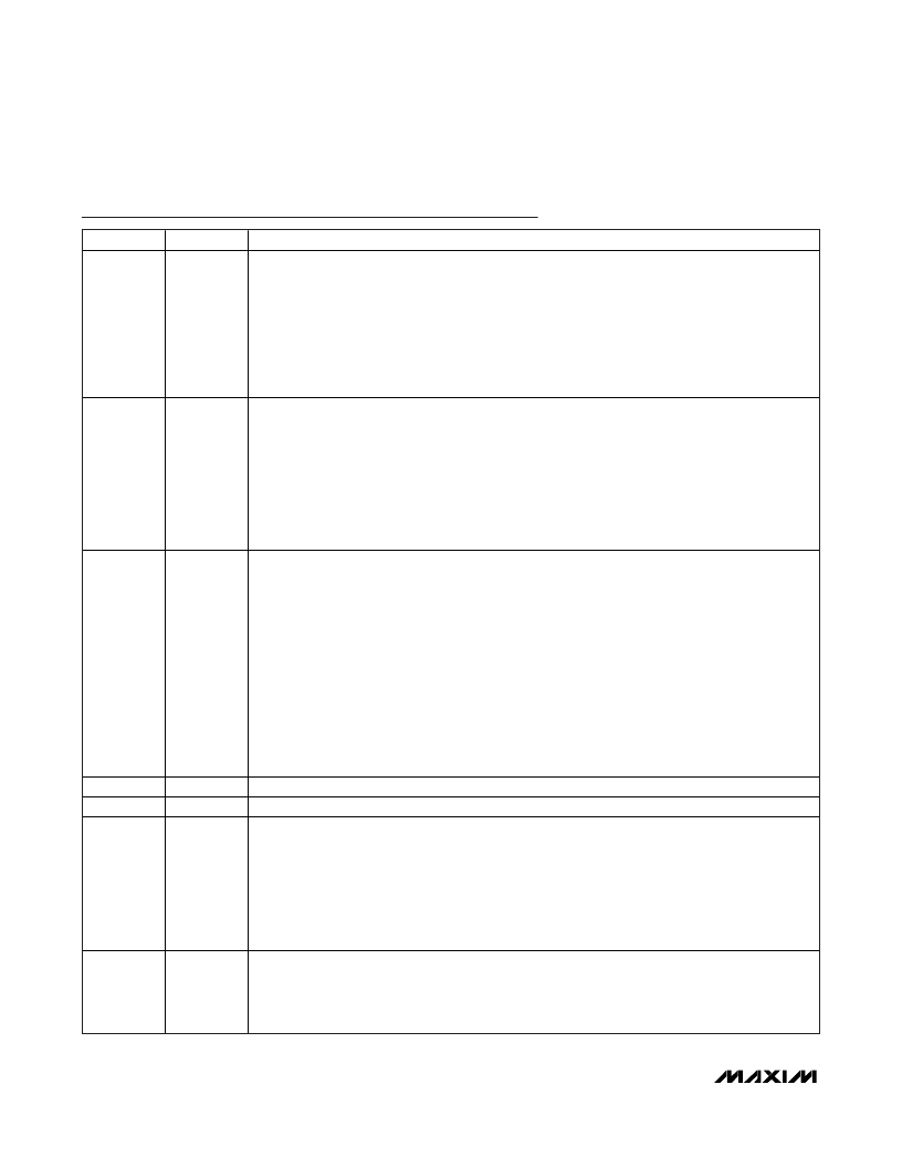
�Pin� Description� (continued)�
�PIN�
�7�
�8�
�9�
�NAME�
�PHASEGD�
�PGDIN�
�FB�
�FUNCTION�
�Open-Drain Phase-Good Output. Used to signal the system that one of the two phases either has a�
�fault� condition� or� is� not� matched� with� the� other.� Detection� is� done� by� identifying� the� need� for� a�
�large� (more� than� 40%)� on-time� difference� between� phases� to� achieve� or� move� towards� current�
�balance. PHASEGD is low in shutdown, and when phase 2 is disabled by connecting CSP2 to V� CC� .�
�PHASEGD� is� forced� high� impedance� whenever� the� slew-rate� controller� is� active� (output� voltage�
�transitions), and when phase 2 is disabled by the DPRSLPVR and/or PSI inputs. When phase 2 is�
�reenabled,� PHASEGD� stays� high� impedance� for� 32� DH2� pulses,� after� which� it� monitors� the�
�difference between the on-times of the two phases. PHASEGD is also forced high impedance when�
�V� FB� is� below� 0.5V.�
�Power-Good� Logic� Input.� Indicates� the� power� status� of� other� system� rails� and� used� for� supply�
�sequencing.� Connect� this� pin� to� the� 5V� supply� rail� or� float� it� if� the� feature� is� not� needed.� During�
�startup,� after� soft-starting� to� the� boot� voltage,� the� output� voltage� remains� at� V� BOOT� ,� and� the� CLKEN�
�and� PWRGD� outputs� remain� high� and� low,� respectively,� as� long� as� the� PGDIN� input� stays� low.�
�When� PGDIN� later� goes� high,� the� output� is� allowed� to� transition� to� the� voltage� set� by� the� VID� code,�
�and� CLKEN� is� allowed� to� go� low.� During� normal� operation,� if� PGDIN� goes� low,� the� controller�
�immediately� forces� CLKEN� high� and� PWRGD� low,� and� slews� the� output� to� the� boot� voltage� while� in�
�2-phase� skip� mode� at� 1/8� the� normal� slew� rate� set� by� the� TIME� resistor.� The� output� then� stays� at�
�the� boot� voltage� until� the� controller� is� turned� off� or� power� cycled,� or� until� PGDIN� goes� high� again.�
�Feedback� Voltage� Input,� and� Output� of� the� Voltage-Positioning� Transconductance� Amplifier.� The�
�voltage� at� the� FB� pin� is� compared� with� the� slew-rate-controlled� target� voltage� by� the� error�
�comparator� (fast� regulation� loop),� as� well� as� by� the� internal� voltage� integrator� (slow,� accurate�
�regulation loop). Having sufficient ripple signal at FB that is in-phase with the sum of the inductor�
�currents� is� essential� for� cycle-by-cycle� stability.�
�Connect resistor R� FB� between FB and VPS to set the droop based on the voltage-positioning gain�
�requirements:�
�R� FB� =� R� DROOP� /[R� SENSE� x� G� m(FB)� ]�
�where� R� DROOP� is� the� desired� voltage-positioning� slope,� G� m(FB)� =� 1.2mS� typ,� and� R� SENSE� is� the�
�effective current-sense resistance that is used to provide the (CSPAVG, CSN_) current-sense voltage.�
�If� lossless� sensing� (inductor� DCR� sensing)� is� used,� consider� using� a� thermistor� as� part� of� the�
�CSPAVG filter network to minimize the temperature dependence of the voltage-positioning slope.�
�FB� is� high� impedance� in� shutdown.�
�10�
�VPS�
�Internally� Shorted� to� OUTS� Through� a� 10�
�Resistance�
�11�
�12�
�13�
�SGND�
�TIME�
�ILIM�
�Internally� Shorted� SGND� (Pin� 11)� to� AGND� (Pin� 21)�
�Slew-Rate Adjustment Pin. The total resistance R� TIME� from TIME to GND sets the internal slew rate.�
�SLEW� RATE� =� (12.5mV/μs)� x� (71.5k� /R� TIME� )� where� R� TIME� is� between� 35.7k�
�and� 178k� .�
�This “normal” slew rate applies to transitions into and out of the low-power pulse-skipping modes�
�and to the transition from boot mode to VID. The slew rate for startup and for entering shutdown is�
�always 1/8 of normal. If DPRSLPVR and DPRSTP are both high, then the slew rate is reduced to 1/4�
�of normal. If the VID DAC inputs are clocked, the slew rate for all other VID transitions is set by the�
�rate at which they are clocked, up to a maximum slew rate equal to the normal slew rate defined�
�above.�
�Current-Limit� Adjust� Input.� The� valley� positive� current-limit� threshold� voltages� at� V(CSP_,� CSN_)�
�are precisely 1/10 the differential voltage V(TIME, ILIM) over a 0.1V to 0.5V range of V(TIME, ILIM).�
�The� valley� negative� current-limit� thresholds� are� typically� -125%� of� the� corresponding� valley�
�positive� current-limit� thresholds.� Connect� ILIM� to� V� CC� to� get� the� default� current-limit� threshold�
�setting� of� 22.5mV� typ.�
�16�
�______________________________________________________________________________________�
�相关PDF资料 |
PDF描述 |
|---|---|
| BAV99W,115 | DIODE ARRAY 100V 130MA SOT323 |
| ATS049B | CRYSTAL 4.9152 MHZ 18PF |
| ATS221B | CRYSTAL 22.1184 MHZ 18 PF FUND |
| ATS20A | CRYSTAL 20.0 MHZ 20 PF FUND |
| ATS073B | CRYSTAL 7.3728 MHZ 18 PF FUND |
相关代理商/技术参数 |
参数描述 |
|---|---|
| MAX17411GTM+ | 功能描述:电流型 PWM 控制器 IMVP7 CPU & Graphics Controller RoHS:否 制造商:Texas Instruments 开关频率:27 KHz 上升时间: 下降时间: 工作电源电压:6 V to 15 V 工作电源电流:1.5 mA 输出端数量:1 最大工作温度:+ 105 C 安装风格:SMD/SMT 封装 / 箱体:TSSOP-14 |
| MAX17411GTM+T | 功能描述:电流型 PWM 控制器 IMVP7 CPU & Graphics Controller RoHS:否 制造商:Texas Instruments 开关频率:27 KHz 上升时间: 下降时间: 工作电源电压:6 V to 15 V 工作电源电流:1.5 mA 输出端数量:1 最大工作温度:+ 105 C 安装风格:SMD/SMT 封装 / 箱体:TSSOP-14 |
| MAX17411RGTM+ | 功能描述:电流型 PWM 控制器 RoHS:否 制造商:Texas Instruments 开关频率:27 KHz 上升时间: 下降时间: 工作电源电压:6 V to 15 V 工作电源电流:1.5 mA 输出端数量:1 最大工作温度:+ 105 C 安装风格:SMD/SMT 封装 / 箱体:TSSOP-14 |
| MAX17411RGTM+T | 功能描述:电流型 PWM 控制器 RoHS:否 制造商:Texas Instruments 开关频率:27 KHz 上升时间: 下降时间: 工作电源电压:6 V to 15 V 工作电源电流:1.5 mA 输出端数量:1 最大工作温度:+ 105 C 安装风格:SMD/SMT 封装 / 箱体:TSSOP-14 |
| MAX17411RGTM+TW | 功能描述:电流型 PWM 控制器 RoHS:否 制造商:Texas Instruments 开关频率:27 KHz 上升时间: 下降时间: 工作电源电压:6 V to 15 V 工作电源电流:1.5 mA 输出端数量:1 最大工作温度:+ 105 C 安装风格:SMD/SMT 封装 / 箱体:TSSOP-14 |
发布紧急采购,3分钟左右您将得到回复。