- 您现在的位置:买卖IC网 > PDF目录20357 > MCZ33937EK (Freescale Semiconductor)IC PRE-DRIVER 3PHASE 54-SOIC PDF资料下载
参数资料
| 型号: | MCZ33937EK |
| 厂商: | Freescale Semiconductor |
| 文件页数: | 34/48页 |
| 文件大小: | 0K |
| 描述: | IC PRE-DRIVER 3PHASE 54-SOIC |
| 标准包装: | 26 |
| 系列: | SMARTMOS™ |
| 配置: | 3 相桥 |
| 输入类型: | 非反相 |
| 延迟时间: | 265ns |
| 电流 - 峰: | 600mA |
| 配置数: | 1 |
| 输出数: | 3 |
| 高端电压 - 最大(自引导启动): | 15V |
| 电源电压: | 8 V ~ 40 V |
| 工作温度: | -40°C ~ 135°C |
| 安装类型: | 表面贴装 |
| 封装/外壳: | 54-BSSOP(0.295",7.50mm 宽)裸露焊盘 |
| 供应商设备封装: | 54-SOICW-EP |
| 包装: | 管件 |
第1页第2页第3页第4页第5页第6页第7页第8页第9页第10页第11页第12页第13页第14页第15页第16页第17页第18页第19页第20页第21页第22页第23页第24页第25页第26页第27页第28页第29页第30页第31页第32页第33页当前第34页第35页第36页第37页第38页第39页第40页第41页第42页第43页第44页第45页第46页第47页第48页
�� �
�
�FUNCTIONAL� DEVICE� OPERATION�
�LOGIC� COMMANDS� AND� REGISTERS�
�DEADTIME� COMMAND�
�Deadtime� prevents� the� turn-on� of� both� transistors� in� the�
�same� phase� until� the� deadtime� has� expired.� The� deadtime�
�timer� starts� when� a� FET� is� commanded� off� (see� Figure 6� and�
�Figure� 13� ).� The� deadtime� control� is� disabled� by� enabling� the�
�FULLON� mode.�
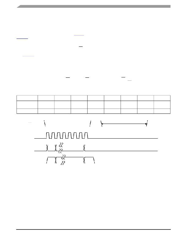
�The� deadtime� is� set� by� sending� the� DEADTIME� command�
�(100x� xxx1),� and� then� sending� a� calibration� pulse� of� CS.� This�
�pulse� must� be� 16� times� longer� than� the� required� deadtime�
�(see� Figure� 19� ).� Deadtime� is� measured� in� cycle� times� of� the�
�internal� time� base,� f� TB� .� This� measurement� is� divided� by� 16�
�and� stored� in� an� internal� register� to� provide� the� reference� for�
�timing� the� deadtime� between� high� and� low� gate� transactions�
�in� the� same� phase.�
�For� example:� the� internal� time� base� is� running� at� 20� MHz�
�and� a� 1.5� μs� deadtime� is� required.� First� a� DEADTIME�
�command� is� sent� (using� the� SPI),� then� a� CS� is� sent.� The� CS�
�pulse� is� 16*1.5� =� 24� μs� wide.� The� IC� measures� this� pulse� as�
�24000� ns/50� ns� =� 480� clock� cycles� and� stores� 480/16� =� 30� in�
�Table� 13.� .DEADTIME� Command�
�the� deadtime� register.� Until� the� next� deadtime� calibration� is�
�performed,� 30� clock� cycles� will� separate� the� turn� off� and� turn�
�on� gate� signals� in� the� same� phase.� The� worst� case� error�
�immediately� after� calibration� will� be� +0/-1� time� base� cycle,� for�
�this� example� +0� ns/-50� ns.� Note� that� if� the� internal� time� base�
�drifts,� the� effect� on� dead� time� will� scale� directly.�
�Sending� a� ZERO� DEADTIME� command� (100x� xxx0)� sets�
�the� deadtime� timer� to� 0.� However,� simultaneous� turn-on� of�
�High� Side� and� Low� Side� FETs� in� the� same� phase� is� still�
�prevented� unless� the� FULLON� command� has� been�
�transmitted.� There� is� no� calibration� pulse� expected� after�
�receiving� the� ZERO� DEADTIME� command.�
�After� RESET,� deadtime� is� set� to� the� maximum� value� of� 255�
�time� base� cycles� (typically� 15� μs).�
�The� IC� ignores� any� SPI� data� that� is� sent� during� the�
�calibration� pulse.� If� there� are� any� transitions� on� SI� or� SCLK�
�while� the� Deadtime� CS� pulse� is� low,� a� Framing� Error� will� be�
�generated,� however,� the� CS� pulse� will� be� used� to� calibrate�
�the� deadtime�
�SPI� Data� Bits�
�Write�
�7�
�1�
�6�
�0�
�5�
�0�
�4�
�x�
�3�
�x�
�2�
�x�
�1�
�x�
�0�
�ZERO/�
�CALIBRATE�
�Reset�
�x�
�x�
�x�
�x�
�CS�
�SCLK�
�SI�
�CS�
�SCLK�
�SI�
�Deadtime�
�DEADTIME�
�Command�
�Deadtime� Calibration� Pulse� Pulse�
�SO�
�SO�
�Figure� 19.� Deadtime� Calibration�
�33937A�
�Analog� Integrated� Circuit� Device� Data�
�34�
�Freescale� Semiconductor�
�相关PDF资料 |
PDF描述 |
|---|---|
| 345-100-527-204 | CARDEDGE 100POS DUAL .100 GREEN |
| T95D107K016LSAS | CAP TANT 100UF 16V 10% 2917 |
| HCC05DRTS-S13 | CONN EDGECARD 10POS .100 EXTEND |
| VI-264-CX-S | CONVERTER MOD DC/DC 48V 75W |
| 345-100-527-202 | CARDEDGE 100POS DUAL .100 GREEN |
相关代理商/技术参数 |
参数描述 |
|---|---|
| MCZ33937EK/R2 | 制造商:FREESCALE 制造商全称:Freescale Semiconductor, Inc 功能描述:Three Phase Field Effect Transistor Pre-driver |
| MCZ33937EKR2 | 功能描述:功率驱动器IC THREE PHASE PRE DRIVER RoHS:否 制造商:Micrel 产品:MOSFET Gate Drivers 类型:Low Cost High or Low Side MOSFET Driver 上升时间: 下降时间: 电源电压-最大:30 V 电源电压-最小:2.75 V 电源电流: 最大功率耗散: 最大工作温度:+ 85 C 安装风格:SMD/SMT 封装 / 箱体:SOIC-8 封装:Tube |
| MCZ33970EG | 功能描述:马达/运动/点火控制器和驱动器 DUAL GAGE DRVR IMP DAMP RoHS:否 制造商:STMicroelectronics 产品:Stepper Motor Controllers / Drivers 类型:2 Phase Stepper Motor Driver 工作电源电压:8 V to 45 V 电源电流:0.5 mA 工作温度:- 25 C to + 125 C 安装风格:SMD/SMT 封装 / 箱体:HTSSOP-28 封装:Tube |
| MCZ33970EG | 制造商:Freescale Semiconductor 功能描述:IC STEPPER MOTOR GAUGE DRIVER SPI |
| MCZ33970EGR2 | 功能描述:马达/运动/点火控制器和驱动器 DUAL GAGE DRVR IMP DAMP RoHS:否 制造商:STMicroelectronics 产品:Stepper Motor Controllers / Drivers 类型:2 Phase Stepper Motor Driver 工作电源电压:8 V to 45 V 电源电流:0.5 mA 工作温度:- 25 C to + 125 C 安装风格:SMD/SMT 封装 / 箱体:HTSSOP-28 封装:Tube |
发布紧急采购,3分钟左右您将得到回复。