- 您现在的位置:买卖IC网 > PDF目录17033 > MPC8308-KIT (Freescale Semiconductor)KIT EVALUATION FOR MPC830X PDF资料下载
参数资料
| 型号: | MPC8308-KIT |
| 厂商: | Freescale Semiconductor |
| 文件页数: | 30/83页 |
| 文件大小: | 0K |
| 描述: | KIT EVALUATION FOR MPC830X |
| 标准包装: | 1 |
| 系列: | PowerQUICC II™ PRO |
| 类型: | MPU |
| 适用于相关产品: | MPC8308 |
| 所含物品: | 板,线缆,CD,电源 |
第1页第2页第3页第4页第5页第6页第7页第8页第9页第10页第11页第12页第13页第14页第15页第16页第17页第18页第19页第20页第21页第22页第23页第24页第25页第26页第27页第28页第29页当前第30页第31页第32页第33页第34页第35页第36页第37页第38页第39页第40页第41页第42页第43页第44页第45页第46页第47页第48页第49页第50页第51页第52页第53页第54页第55页第56页第57页第58页第59页第60页第61页第62页第63页第64页第65页第66页第67页第68页第69页第70页第71页第72页第73页第74页第75页第76页第77页第78页第79页第80页第81页第82页第83页
MPC8308 PowerQUICC II Pro Processor Hardware Specification, Rev. 3
36
Freescale Semiconductor
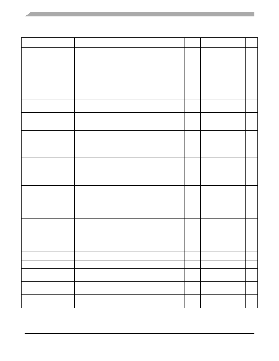
PCI Express
Absolute delta of DC
common mode voltage
during L0 and electrical idle
VTX-CM-DC- ACTIVE-
IDLE-DELTA
|VTX-CM-DC (during L0) - VTX-CM-Idle-DC
(During Electrical Idle)|<=100 mV
VTX-CM-DC = DC(avg) of |VTX-D+ +
VTX-D-|/2 [L0]
VTX-CM-Idle-DC = DC(avg) of |VTX-D+ +
VTX-D-|/2 [Electrical Idle]
0
—
100
mV
2
Absolute delta of DC
common mode between D+
and D–
VTX-CM-DC-LINE-
DELTA
|VTX-CM-DC-D+ - VTX-CM-DC-D-| <= 25 mV
VTX-CM-DC-D+ = DC(avg) of |VTX-D+|
VTX-CM-DC-D- = DC(avg) of |VTX-D-|
0—
25
mV
2
Electrical idle differential
peak output voltage
VTX-IDLE-DIFFp
VPEEIDPTX = |VTX-IDLE-D+ -VTX-IDLE-D-|
<= 20 mV
0—
20
mV
2
Amount of voltage change
allowed during receiver
detection
VTX-RCV-DETECT The total amount of voltage change that
a transmitter can apply to sense whether
a low impedance Receiver is present.
—600
—
mV
6
TX DC common mode
voltage
VTX-DC-CM
The allowed DC Common Mode voltage
under any conditions.
—3.6
—
V
6
TX short circuit current limit
ITX-SHORT
The total current the Transmitter can
provide when shorted to its ground
——
90
mA
—
Minimum time spent in
electrical idle
TTX-IDLE-MIN
Minimum time a Transmitter must be in
Electrical Idle Utilized by the Receiver to
start looking for an Electrical Idle Exit
after successfully receiving an Electrical
Idle ordered set
50
—
UI
—
Maximum time to transition
to a valid electrical idle after
sending an electrical idle
ordered set
TTX-IDLE-SET-TO-ID
LE
After sending an Electrical Idle ordered
set, the Transmitter must meet all
Electrical Idle Specifications within this
time. This is considered a debounce time
for the Transmitter to meet Electrical Idle
after transitioning from L0.
——
20
UI
—
Maximum time to transition
to valid TX specifications
after leaving an electrical
idle condition
TTX-IDLE-TO-DIFF-D
ATA
Maximum time to meet all TX
specifications when transitioning from
Electrical Idle to sending differential
data. This is considered a debounce
time for the TX to meet all TX
specifications after leaving Electrical Idle
——
20
UI
—
Differential return loss
RLTX-DIFF
Measured over 50 MHz to 1.25 GHz.
12
—
dB
4
Common mode return loss
RLTX-CM
Measured over 50 MHz to 1.25 GHz.
6
—
dB
4
DC differential TX
impedance
ZTX-DIFF-DC
TX DC Differential mode Low
Impedance
80
100
120
—
Transmitter DC impedance
ZTX-DC
Required TX D+ as well as D- DC
Impedance during all states
40
—
—
Lane-to-Lane output skew
LTX-SKEW
Static skew between any two Transmitter
Lanes within a single Link
—
500 + 2
UI
ps
—
Table 34. Differential Transmitter (TX) Output Specifications (continued)
Parameter
Symbol
Comments
Min
Typical
Max
Units Note
相关PDF资料 |
PDF描述 |
|---|---|
| EBA22DTMH | CONN EDGECARD 44POS R/A .125 SLD |
| EBA22DTMD | CONN EDGECARD 44POS R/A .125 SLD |
| EBM36DCSN | CONN EDGECARD 72POS DIP .156 SLD |
| EBA22DTBN | CONN EDGECARD 44POS R/A .125 SLD |
| EBM36DCSH | CONN EDGECARD 72POS DIP .156 SLD |
相关代理商/技术参数 |
参数描述 |
|---|---|
| MPC8308-NSG | 功能描述:开发板和工具包 - 其他处理器 MPC8308-NSG RoHS:否 制造商:Freescale Semiconductor 产品:Development Systems 工具用于评估:P3041 核心:e500mc 接口类型:I2C, SPI, USB 工作电源电压: |
| MPC8308-NSG | 制造商:Freescale Semiconductor 功能描述:MPC8308-NSG*NIC* |
| MPC8308-RDB | 功能描述:开发板和工具包 - 其他处理器 Refer. Board MPC8308 RoHS:否 制造商:Freescale Semiconductor 产品:Development Systems 工具用于评估:P3041 核心:e500mc 接口类型:I2C, SPI, USB 工作电源电压: |
| MPC8308-RDB-PROMO | 制造商:Freescale 功能描述:Motherboards MPC8308 PowerQuicc II DDR2 10Mbps/100Mbps/1000Mbps Linux Kernel |
| MPC8308-SOM | 功能描述:开发板和工具包 - 其他处理器 For MPC8308 Ethernet USB 32bit RoHS:否 制造商:Freescale Semiconductor 产品:Development Systems 工具用于评估:P3041 核心:e500mc 接口类型:I2C, SPI, USB 工作电源电压: |
发布紧急采购,3分钟左右您将得到回复。