- 您现在的位置:买卖IC网 > PDF目录296796 > PCM9211PTR (TEXAS INSTRUMENTS INC) DATACOM, TOKEN RING TRANSCEIVER, PQFP48 PDF资料下载
参数资料
| 型号: | PCM9211PTR |
| 厂商: | TEXAS INSTRUMENTS INC |
| 元件分类: | 网络接口 |
| 英文描述: | DATACOM, TOKEN RING TRANSCEIVER, PQFP48 |
| 封装: | GREEN, PLASTIC, LQFP-48 |
| 文件页数: | 43/121页 |
| 文件大小: | 1219K |
| 代理商: | PCM9211PTR |
第1页第2页第3页第4页第5页第6页第7页第8页第9页第10页第11页第12页第13页第14页第15页第16页第17页第18页第19页第20页第21页第22页第23页第24页第25页第26页第27页第28页第29页第30页第31页第32页第33页第34页第35页第36页第37页第38页第39页第40页第41页第42页当前第43页第44页第45页第46页第47页第48页第49页第50页第51页第52页第53页第54页第55页第56页第57页第58页第59页第60页第61页第62页第63页第64页第65页第66页第67页第68页第69页第70页第71页第72页第73页第74页第75页第76页第77页第78页第79页第80页第81页第82页第83页第84页第85页第86页第87页第88页第89页第90页第91页第92页第93页第94页第95页第96页第97页第98页第99页第100页第101页第102页第103页第104页第105页第106页第107页第108页第109页第110页第111页第112页第113页第114页第115页第116页第117页第118页第119页第120页第121页
C2
C1
R1
FILT
AGND
DGND
Charge
Pump
VCO
PCM9211
PLLSection
SBAS495 – JUNE 2010
www.ti.com
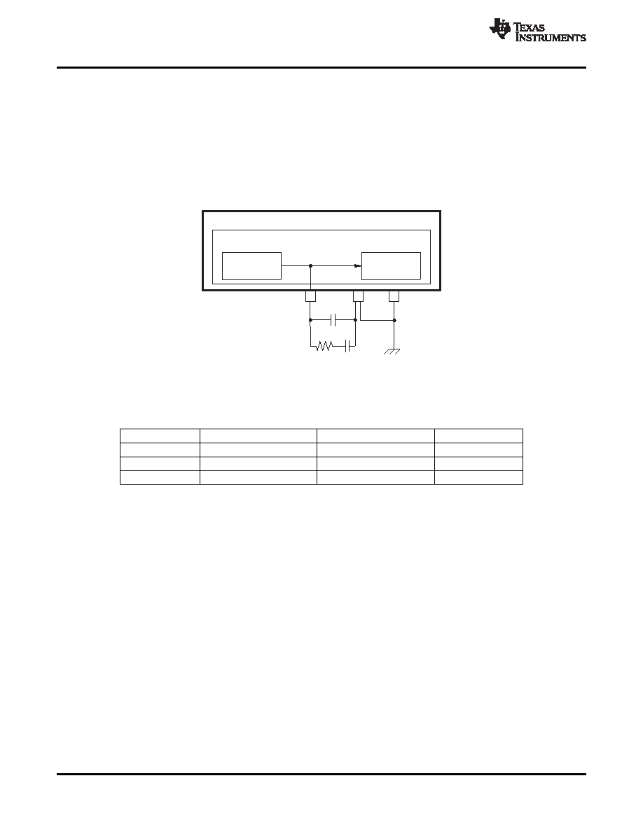
DIR and PLL Loop Filter Details
The PCM9211 incorporates a PLL for generating clocks synchronized with the input biphase signal (S/PDIF).
The onboard PLL requires an external loop filter. The components and configuration shown in Figure 20 and
Table 6 are recommended for optimal performance, with these considerations:
The resistor and capacitors that configure the filter should be located and routed as close as possible to the
PCM9211. The external loop filter must be placed on the FILT pins.
The GND node of the external loop filter must be directly connected with AGND pin of the PCM9211; it must
be not combined with other signals.
Figure 20 shows the configuration of the external loop filter and the connection with the PCM9211.
Figure 20. Loop Filter Connection
The recommended value of loop filter components is shown in Table 6.
Table 6. Recommended Value of Loop Filter Components
REF. NO.
RECOMMENDED VALUE
TYPE
TOLERANCE
R1
680
Ω
Metal film or carbon
≤ 5%
C1
0.068 F
Film or ceramic (CH or C0G)
≤ 5%
C2
0.0047 F
Film or ceramic (CH or C0G)
≤ 5%
External (XTI) Clocks, Oscillators, and Supporting Circuitry
An external clock source (CMOS or crystal/resonator) is known as the XTI source. The XTI source can be either
a CMOS logic source, or a crystal resonator (internal circuitry in the PCM9211 can start the crystal resonating).
Whichever clock source is used, it must be 24.576 MHz.
The PCM9211 uses the XTI source as a reference clock in order to calculate the sampling frequency of the
incoming S/PDIF stream. It is also used as the clock source in XTI clock source mode.
When using a resonator as an XTI source, the following points should be considered:
The 24.576-MHz resonator should be connected between the XTI and XTO pins
The resonator should be a fundamental mode type
A crystal or ceramic resonator can be used as the XTI source
The values of the load capacitors CL1 and CL2 and the current limiting resistor Rd all depend on the
characteristics of the resonator
No external feedback resistor between the XTI and XTO pins is required, because the resistor is integrated
into the device
No loads other than the resonator should be used on the XTO pin
When using an external oscillation circuit with a CMOS output, the following points should be considered:
Always supply a 24.576-MHz clock on the XTI pin
Only 3.3 V is supported on the XTI pin; 5 V is not supported
XTO should be left floating
28
Copyright 2010, Texas Instruments Incorporated
Product Folder Link(s): PCM9211
相关PDF资料 |
PDF描述 |
|---|---|
| PCM9211PT | DATACOM, TOKEN RING TRANSCEIVER, PQFP48 |
| PCN11MF | STRIP TERMINAL BLOCK, 1 DECK |
| PCN12E-32S-2.54DSA | 32 CONTACT(S), FEMALE, STRAIGHT TWO PART EURO CONNECTOR, SOLDER, SOCKET |
| PCN12E-44S-2.54DSA | 44 CONTACT(S), FEMALE, STRAIGHT TWO PART EURO CONNECTOR, SOLDER, SOCKET |
| PCN12E-50S-2.54DSA | 50 CONTACT(S), FEMALE, STRAIGHT TWO PART EURO CONNECTOR, SOLDER, SOCKET |
相关代理商/技术参数 |
参数描述 |
|---|---|
| PCM-93 | 功能描述:电线鉴定 Pre-Printed WM Card, Vinyl Cloth, .22" W RoHS:否 制造商:TE Connectivity / Q-Cees 产品:Labels and Signs 类型: 材料:Vinyl 颜色:Blue 宽度:0.625 in 长度:1 in |
| PCM-9342 | 制造商:ADVANTECH 制造商全称:Advantech Co., Ltd. 功能描述:X86 SoC 3.5" SBC with VGA, LCD, LAN, USB, SATA, CF, PC/104 |
| PCM-9342F-64A1E | 制造商:ADVANTECH 制造商全称:Advantech Co., Ltd. 功能描述:X86 SoC 3.5" SBC with VGA, LCD, LAN, USB, SATA, CF, PC/104 |
| PCM-9342FZ2-64A1E | 制造商:ADVANTECH 制造商全称:Advantech Co., Ltd. 功能描述:X86 SoC 3.5" SBC with VGA, LCD, LAN, USB, SATA, CF, PC/104 |
| PCM-9342L-64A1E | 制造商:ADVANTECH 制造商全称:Advantech Co., Ltd. 功能描述:X86 SoC 3.5" SBC with VGA, LCD, LAN, USB, SATA, CF, PC/104 |
发布紧急采购,3分钟左右您将得到回复。