- 您现在的位置:买卖IC网 > PDF目录296796 > PCM9211PTR (TEXAS INSTRUMENTS INC) DATACOM, TOKEN RING TRANSCEIVER, PQFP48 PDF资料下载
参数资料
| 型号: | PCM9211PTR |
| 厂商: | TEXAS INSTRUMENTS INC |
| 元件分类: | 网络接口 |
| 英文描述: | DATACOM, TOKEN RING TRANSCEIVER, PQFP48 |
| 封装: | GREEN, PLASTIC, LQFP-48 |
| 文件页数: | 48/121页 |
| 文件大小: | 1219K |
| 代理商: | PCM9211PTR |
第1页第2页第3页第4页第5页第6页第7页第8页第9页第10页第11页第12页第13页第14页第15页第16页第17页第18页第19页第20页第21页第22页第23页第24页第25页第26页第27页第28页第29页第30页第31页第32页第33页第34页第35页第36页第37页第38页第39页第40页第41页第42页第43页第44页第45页第46页第47页当前第48页第49页第50页第51页第52页第53页第54页第55页第56页第57页第58页第59页第60页第61页第62页第63页第64页第65页第66页第67页第68页第69页第70页第71页第72页第73页第74页第75页第76页第77页第78页第79页第80页第81页第82页第83页第84页第85页第86页第87页第88页第89页第90页第91页第92页第93页第94页第95页第96页第97页第98页第99页第100页第101页第102页第103页第104页第105页第106页第107页第108页第109页第110页第111页第112页第113页第114页第115页第116页第117页第118页第119页第120页第121页
InternalLOCK
Ln
LRCKO(I 2S)
MUTE(Low)
ERROR
DOUT
Parityerror
Interpolationprocessingbypreviousdata
InternalLOCK
LRCKO(I 2S)
ERROR
DOUT
Parityerror
[FORPCMSIGNAL]
[FORNON -PCMSIGNAL ]
Rn
Ln+1
Rn+1
Ln+1
Rn+2
Rn+3
Ln+3
Ln
MUTE(Low)
Rn
Ln+1
Rn+1
Ln+2
Rn+2
Rn+3
Ln+3
SBAS495 – JUNE 2010
www.ti.com
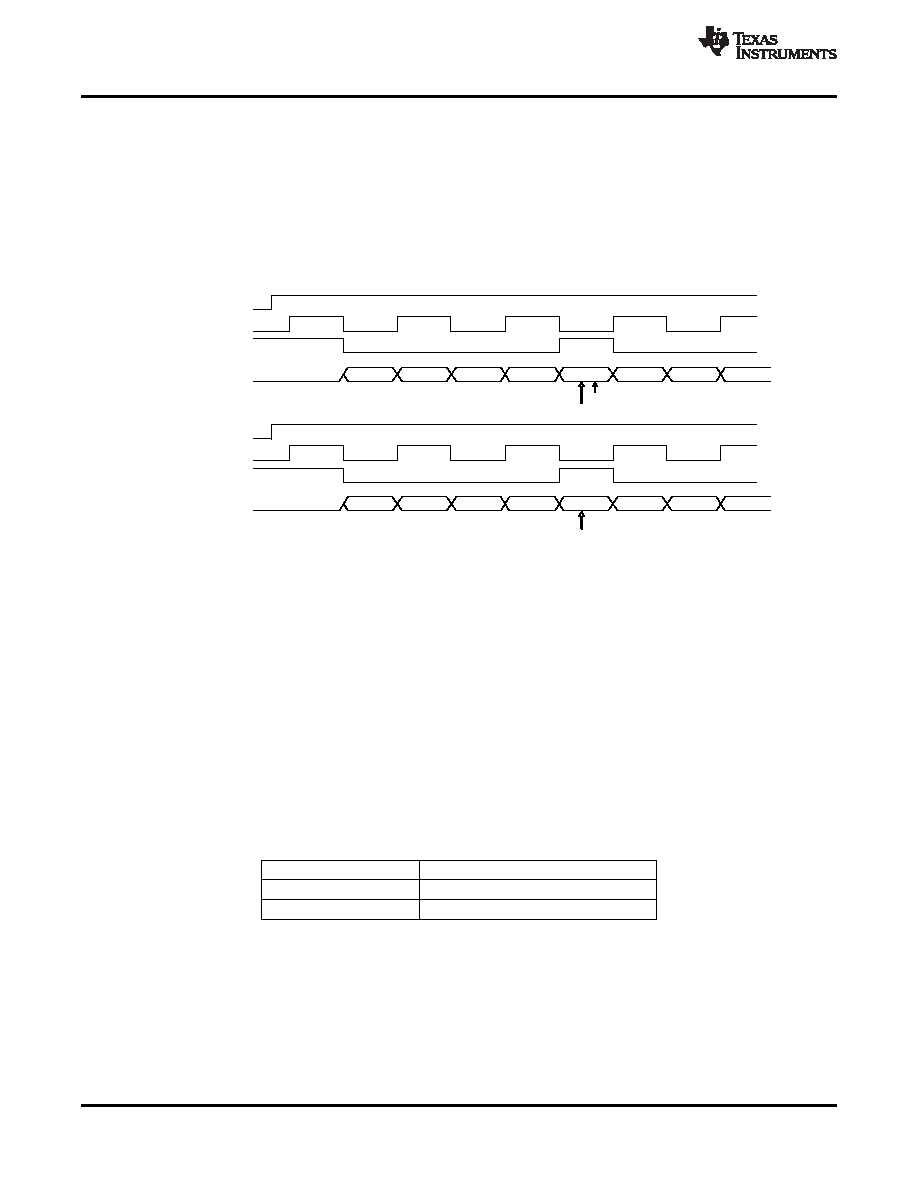
DIR: Parity Error Processing
Error detection and processing for parity errors behave in the following manner:
For PCM data, when an error is detected (for example, a parity error), then the data from the previous sample
are repeated. This sequence is shown in Figure 26, where sample Ln+1 is repeated because the incoming
data (Ln+2) had an error.
For non-PCM data, the data are output as is with no changes. (Non-PCM data implies data which has
Channel Status bit 1 = '1'.)
Figure 26 shows the processing for parity error occurrence.
Figure 26. Processing for Parity Error Occurrence
The PCM9211 handles parity errors as directed by the 23h/PRTPRO[1:0] registers.
When set to '01', if the error is received eight times sequentially, the DIR output is muted on the next error. Until
the mute is enabled, the previously accurate sample is repeated. This function is only valid for PCM data.
When set to '10', the device behaves in exactly the same way as it does when set to '01'. However, this function
is enabled for both PCM and non-PCM data.
When set to '00', the device ignores parity errors and continues to output whatever data comes into the device.
The setting on '11' is reserved.
DIR: Errors and Interrupts
The PCM9211 has two pins that are used to inform the system DSP or controller that there is an error, or an
interrupt that it should be aware of.
The ERR/INT0 and NPCM/INT1 pins can be configured in these ways:
HARDWARE PIN
OPTIONS
ERR/INTO0
DIR Error (default), INT0 or Hi-Z
NPCM/INT1
DIR NPCM (default), INT1 or Hi-Z
When configured as direct DIR error connections (ERR, NPCM), the system audio processor typically treats
them as dedicated interrupt pins to change or control audio processing software. An example would be that the
system may mute if an ERR signal is detected. Another example is that if the DSP receives an NPCM interrupt, it
begins looking for AC-3 or DTS preambles in the incoming encoded S/PDIF stream.
For more advanced users, the two pins can be set up as interrupt sources. The seven interrupt sources
(ERROR, NPCM, DTS-CD/LD, Emphasis, Channel Status Start, Burst Preamble Start, fS Calculator Complete)
can be masked into Registers INT0 and INT1.
32
Copyright 2010, Texas Instruments Incorporated
Product Folder Link(s): PCM9211
相关PDF资料 |
PDF描述 |
|---|---|
| PCM9211PT | DATACOM, TOKEN RING TRANSCEIVER, PQFP48 |
| PCN11MF | STRIP TERMINAL BLOCK, 1 DECK |
| PCN12E-32S-2.54DSA | 32 CONTACT(S), FEMALE, STRAIGHT TWO PART EURO CONNECTOR, SOLDER, SOCKET |
| PCN12E-44S-2.54DSA | 44 CONTACT(S), FEMALE, STRAIGHT TWO PART EURO CONNECTOR, SOLDER, SOCKET |
| PCN12E-50S-2.54DSA | 50 CONTACT(S), FEMALE, STRAIGHT TWO PART EURO CONNECTOR, SOLDER, SOCKET |
相关代理商/技术参数 |
参数描述 |
|---|---|
| PCM-93 | 功能描述:电线鉴定 Pre-Printed WM Card, Vinyl Cloth, .22" W RoHS:否 制造商:TE Connectivity / Q-Cees 产品:Labels and Signs 类型: 材料:Vinyl 颜色:Blue 宽度:0.625 in 长度:1 in |
| PCM-9342 | 制造商:ADVANTECH 制造商全称:Advantech Co., Ltd. 功能描述:X86 SoC 3.5" SBC with VGA, LCD, LAN, USB, SATA, CF, PC/104 |
| PCM-9342F-64A1E | 制造商:ADVANTECH 制造商全称:Advantech Co., Ltd. 功能描述:X86 SoC 3.5" SBC with VGA, LCD, LAN, USB, SATA, CF, PC/104 |
| PCM-9342FZ2-64A1E | 制造商:ADVANTECH 制造商全称:Advantech Co., Ltd. 功能描述:X86 SoC 3.5" SBC with VGA, LCD, LAN, USB, SATA, CF, PC/104 |
| PCM-9342L-64A1E | 制造商:ADVANTECH 制造商全称:Advantech Co., Ltd. 功能描述:X86 SoC 3.5" SBC with VGA, LCD, LAN, USB, SATA, CF, PC/104 |
发布紧急采购,3分钟左右您将得到回复。