参数资料
| 型号: | SC16C852VIET,151 |
| 厂商: | NXP Semiconductors |
| 文件页数: | 22/55页 |
| 文件大小: | 0K |
| 描述: | IC UART DUAL W/FIFO 36TFBGA |
| 标准包装: | 490 |
| 特点: | 可编程 |
| 通道数: | 2,DUART |
| FIFO's: | 128 字节 |
| 规程: | RS485 |
| 电源电压: | 2.5V |
| 带自动流量控制功能: | 是 |
| 带IrDA 编码器/解码器: | 是 |
| 带故障启动位检测功能: | 是 |
| 带调制解调器控制功能: | 是 |
| 带CMOS: | 是 |
| 安装类型: | 表面贴装 |
| 封装/外壳: | 36-TFBGA |
| 供应商设备封装: | 36-TFBGA(3.5x3.5) |
| 包装: | 托盘 |
| 其它名称: | 568-5662 935282518151 SC16C852VIET,151-ND SC16C852VIET-S SC16C852VIET-S-ND |
第1页第2页第3页第4页第5页第6页第7页第8页第9页第10页第11页第12页第13页第14页第15页第16页第17页第18页第19页第20页第21页当前第22页第23页第24页第25页第26页第27页第28页第29页第30页第31页第32页第33页第34页第35页第36页第37页第38页第39页第40页第41页第42页第43页第44页第45页第46页第47页第48页第49页第50页第51页第52页第53页第54页第55页
SC16C852V
All information provided in this document is subject to legal disclaimers.
NXP B.V. 2011. All rights reserved.
Product data sheet
Rev. 5 — 21 January 2011
29 of 55
NXP Semiconductors
SC16C852V
Dual UART with 128-byte FIFOs, IrDA, and XScale VLIO bus interface
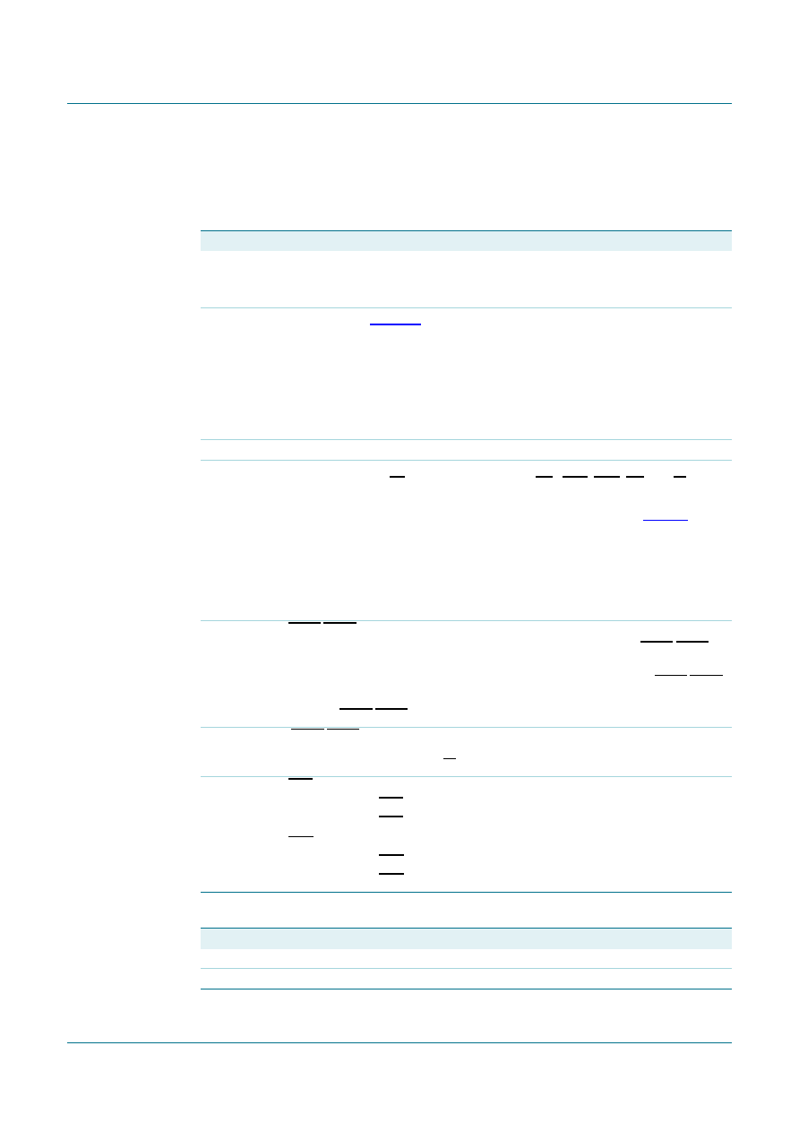
7.6 Modem Control Register (MCR)
This register controls the interface with the modem or a peripheral device.
Table 20.
Modem Control Register bits description
Bit
Symbol Description
7
MCR[7]
Clock select
logic 0 = divide-by-1 clock input
logic 1 = divide-by-4 clock input
6
MCR[6]
IR enable (see Figure 21).
logic 0 = enable the standard modem receive and transmit input/output interface
(normal default condition)
logic 1 = enable infrared IrDA receive and transmit inputs/outputs. While in this
mode, the TX/RX output/inputs are routed to the infrared encoder/decoder. The
data input and output levels will conform to the IrDA infrared interface
requirement. As such, while in this mode, the infrared TX output will be a logic 0
during idle data conditions.
5
MCR[5]
Reserved; set to ‘0’.
4
MCR[4]
Loopback. Enable the local Loopback mode (diagnostics). In this mode the
transmitter output (TX) and the receiver input (RX), CTS, DSR, CD, and RI are
disconnected from the SC16C852V I/O pins. Internally the modem data and
control pins are connected into a loopback data configuration (see Figure 9). In
this mode, the receiver and transmitter interrupts remain fully operational. The
Modem Control Interrupts are also operational, but the interrupts’ sources are
switched to the lower four bits of the Modem Control. Interrupts continue to be
controlled by the IER register.
logic 0 = disable Loopback mode (normal default condition)
logic 1 = enable local Loopback mode (diagnostics)
3
MCR[3]
OP2A/OP2B, INT enable
logic 0 = forces INT (A, B) outputs to the 3-state mode and sets OP2A/OP2B to
a logic 1 (normal default condition)
logic 1 = forces the INT (A, B) outputs to the active mode and sets OP2A/OP2B
to a logic 0
Remark: OP2A/OP2B pins do not exist on the TFBGA36 package.
2
MCR[2]
OP1A/OP1B are not available as an external signal in the SC16C852V. This bit is
instead used in the Loopback mode only. In the Loopback mode, this bit is used to
write the state of the modem RI interface signal.
1
MCR[1]
RTS
logic 0 = force RTS output to a logic 1 (normal default condition)
logic 1 = force RTS output to a logic 0
0
MCR[0]
DTR
logic 0 = force DTR output to a logic 1 (normal default condition)
logic 1 = force DTR output to a logic 0
Table 21.
Interrupt output control
MCR[3]
INT (A, B) output
03-state
1active
相关PDF资料 |
PDF描述 |
|---|---|
| SC16IS741IPW,112 | IC UART 16TSSOP |
| SC16IS750IBS,151 | IC UART I2C/SPI 24-HVQFN |
| SC16IS762IBS,151 | IC UART DUAL I2C/SPI 32-HVQFN |
| SC26C92A1N,112 | IC UART 40-DIP |
| SC28C94A1A,512 | IC UART QUAD W/FIFO 52-PLCC |
相关代理商/技术参数 |
参数描述 |
|---|---|
| SC16C852VIET-G | 功能描述:UART 接口集成电路 1.8V 2CH UART 128B FIFO 5MBPS RoHS:否 制造商:Texas Instruments 通道数量:2 数据速率:3 Mbps 电源电压-最大:3.6 V 电源电压-最小:2.7 V 电源电流:20 mA 最大工作温度:+ 85 C 最小工作温度:- 40 C 封装 / 箱体:LQFP-48 封装:Reel |
| SC16C852VIET-S | 功能描述:UART 接口集成电路 1.8V 2CH UART 128B FIFO 5MBPS RoHS:否 制造商:Texas Instruments 通道数量:2 数据速率:3 Mbps 电源电压-最大:3.6 V 电源电压-最小:2.7 V 电源电流:20 mA 最大工作温度:+ 85 C 最小工作温度:- 40 C 封装 / 箱体:LQFP-48 封装:Reel |
| SC16DP-26 | 制造商:Thomas & Betts 功能描述:SAXXIT CABLE CLIP W/ DRIVE PIN -7 制造商:Belden Inc 功能描述: |
| SC16DP-3Q | 制造商:Thomas & Betts 功能描述:SAXXIT CABLE CLIP W/ DRIVE PIN -8 |
| SC16-FM-M16-NPB-ML-1 | 制造商:HellermannTyton 功能描述: |
发布紧急采购,3分钟左右您将得到回复。