- 您现在的位置:买卖IC网 > PDF目录98079 > SED122ADXA 16 X 60 DOTS DOT MAT LCD DRVR AND DSPL CTLR, UUC165 PDF资料下载
参数资料
| 型号: | SED122ADXA |
| 元件分类: | 显示控制器 |
| 英文描述: | 16 X 60 DOTS DOT MAT LCD DRVR AND DSPL CTLR, UUC165 |
| 封装: | DIE-165 |
| 文件页数: | 6/50页 |
| 文件大小: | 398K |
| 代理商: | SED122ADXA |
第1页第2页第3页第4页第5页当前第6页第7页第8页第9页第10页第11页第12页第13页第14页第15页第16页第17页第18页第19页第20页第21页第22页第23页第24页第25页第26页第27页第28页第29页第30页第31页第32页第33页第34页第35页第36页第37页第38页第39页第40页第41页第42页第43页第44页第45页第46页第47页第48页第49页第50页
4–14
EPSON
SED1220
FUNCTIONAL DESCRIPTION
MPU Interface
Selection of interface type
In the SED1220 Series, data transfer is performed through a 8-bit or 4-bit data bus or a serial data input (SI). By selecting
“High” or “Low” as P/S pin polarity, a parallel data input or a serial data input can be selected as shown in Table 1.
Table 1
Parallel Input
In the SED1220 Series, when parallel input is selected (P/S = “High”), it can be directly connected to the 80 series MPU
bus or 68 series MPU bus, as shown in Table 2, if either “High” or “Low” is selected as RES pin polarity after a reset input,
because the RES pin has an MPU select function.
Selection between 8 bits and 4 bits is performed by command.
Table 2
Interface with 4-bit MPU interface
When data transfer is performed by 4-bit interface (IF = 0), an 8-bit command, data and address are divided into two parts.
Note: When performing writing in succession, reverse a time exceeding the system cycle time (tcyc) and then
perform writing.
Serial interface (P/S = “Low”)
The serial interface consists of a 8-bit shift register and a 3-bit counter and acceptance of an SI input or SCL input is enabled
in the ship selected status (CS = “Low”).
When no chip is selected, the shift register and counter are reset to the initial status.
Serial data is input in the order of D7, D6 .... D0 from the serial data input pin (SI) at the rise of Serial Clock (SCL).
At the rising edge of the 8th serial clock, the serial data is converted into 8-bit parallel data and this data is processed.
The A0 input is used to identify whether the serial data input (SI) is display data or a command. That is, when A0 = “High”,
it is regarded as display data. When A0 = “Low”, it is regarded as a command.
The A0 input is read in and identified at the rise of the 8 x n-th clock of Serial Clock (SCL) after chip selection.
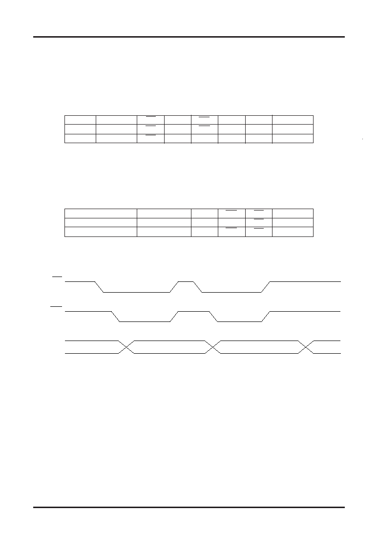
Fig. 1 shows a timing chart of the serial interface.
Regarding the SCL signal, special care must be exercised about terminal reflection and external noise due to a wire length.
We recommend the user to perform an operation check with a real machine.
We also recommend the user to periodically refresh the write status of each command to prevent a malfunction due to noise.
P/S
Type
CS
A0
WR
SI
SCL
D0~D7
“High”
Parallel Input
CS
A0
WR
—
D0~D7
“Low”
Serial Input
CS
A0
H, L
SI
SCL
—
RES input polarity
Type
A0
WR
CS
D0~D7
↓ active
68 series
A0
E
CS
D0~D7
active
80 series
A0
WR
CS
D0~D7
↓
CS
WR
D7 to D4
Upper (D7 to D4)
Lower (D3 to D0)
相关PDF资料 |
PDF描述 |
|---|---|
| SED1278FOD | 16 X 40 DOTS DOT MAT LCD DRVR AND DSPL CTLR, PQFP80 |
| SED1278F | 16 X 40 DOTS DOT MAT LCD DSPL CTLR, PQFP80 |
| SED1330FBA | DOT MAT LCD DSPL CTLR, PQFP60 |
| SED1330FBB | 640 X 256 DOTS DOT MAT LCD DSPL CTLR, PQFP60 |
| SED1335FOA | DOT MAT LCD DSPL CTLR, PQFP60 |
相关代理商/技术参数 |
参数描述 |
|---|---|
| SED1278 | 制造商:未知厂家 制造商全称:未知厂家 功能描述:CMOS DOT MATRIX LCD CONTROLLER DRIVER |
| SED1278D | 制造商:EPSON 制造商全称:EPSON 功能描述:Dot Matrix LCD Controller Driver |
| SED1278D0A | 制造商:未知厂家 制造商全称:未知厂家 功能描述:CMOS DOT MATRIX LCD CONTROLLER DRIVER |
| SED1278D0B | 制造商:未知厂家 制造商全称:未知厂家 功能描述:CMOS DOT MATRIX LCD CONTROLLER DRIVER |
| SED1278D0C | 制造商:未知厂家 制造商全称:未知厂家 功能描述:CMOS DOT MATRIX LCD CONTROLLER DRIVER |
发布紧急采购,3分钟左右您将得到回复。