- 您现在的位置:买卖IC网 > PDF目录98143 > ST10F168-Q3 (STMICROELECTRONICS) 16-BIT, FLASH, 25 MHz, MICROCONTROLLER, PQFP144 PDF资料下载
参数资料
| 型号: | ST10F168-Q3 |
| 厂商: | STMICROELECTRONICS |
| 元件分类: | 微控制器/微处理器 |
| 英文描述: | 16-BIT, FLASH, 25 MHz, MICROCONTROLLER, PQFP144 |
| 封装: | 28 X 28 MM, PLASTIC, QFP-144 |
| 文件页数: | 32/74页 |
| 文件大小: | 479K |
| 代理商: | ST10F168-Q3 |
第1页第2页第3页第4页第5页第6页第7页第8页第9页第10页第11页第12页第13页第14页第15页第16页第17页第18页第19页第20页第21页第22页第23页第24页第25页第26页第27页第28页第29页第30页第31页当前第32页第33页第34页第35页第36页第37页第38页第39页第40页第41页第42页第43页第44页第45页第46页第47页第48页第49页第50页第51页第52页第53页第54页第55页第56页第57页第58页第59页第60页第61页第62页第63页第64页第65页第66页第67页第68页第69页第70页第71页第72页第73页第74页
ST10F168
38/74
17.2 - Synchronous Reset (Warm Reset)
A synchronous reset is triggered when RSTIN pin
is pulled low while VPP pin is at high level. In order
to properly activate the internal reset logic of the
MCU, the RSTIN pin must be held low, at least,
during 4 TCL (2 periods of CPU clock). The I/O
pins are set to high impedance and RSTOUT pin is
driven low. After RSTIN level is detected, a short
duration of 12 TCL (approximately 6 periods of
CPU clock) elapes, during which pending internal
hold states are cancelled and the current internal
access cycle if any is completed. External bus
cycle is aborted. The internal pulldown of RSTIN
pin is activated if bit BDRSTEN of SYSCON reg-
ister was previously set by software. This bit is
always cleared on power-on or after a reset
sequence.
Exit of Synchrounous Reset State
The internal reset sequence starts for 1024 TCL
(512 periods of CPU clock) and RSTIN pin level is
sampled. The reset sequence is extended until
RSTIN
level becomes high. Then, the MCU
restarts. The system configuration is latched from
Port0 and ALE, RD and R/W pins are driven to
their inactive level. The MCU starts program exe-
cution from memory location 00’0000h in code
segment 0. This starting location will typically
point to the general initialization routine. Timing of
synchronous reset sequence are summarized in
Figure 10 and 11.
Notes: 1. RSTIN assertion can be released there.
2. If during the reset condition (RSTIN low), Vpp voltage drops below the threshold voltage (about 2.5V for 5V operation), the
asynchronous reset is then immediately entered.
3. RSTIN rising edge to internal latch of Port0 is 3CPU clock cycles (6 TCL) if the PLL is bypassed and the prescaler is on
(fCPU =fXTAL /2), else it is 4 CPU clock cycles (8 TCL).
4) RSTIN pin is pulled low if bit BDRSTEN (bit 5 of SUSCON register) was previously set by software. Bit BDRSTE N is cleared after
reset.
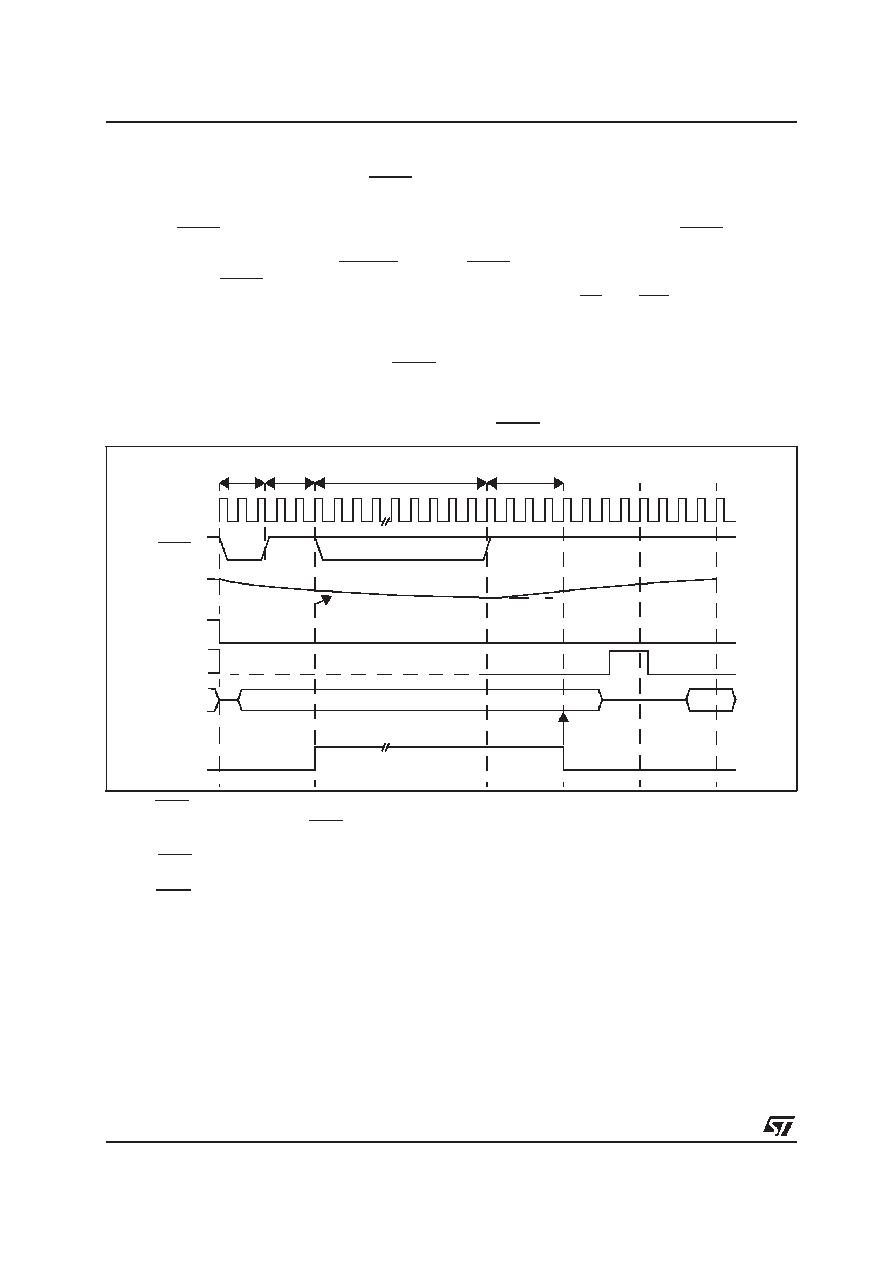
Figure 10 : Synchronous Warm Reset: Short low pulse on RSTIN
CPU Clock
RSTIN
VPP
RSTOUT
ALE
Port0
INST #1
Internal
Reset
Signal
Latching point of Port0
for systemstart-up configuration
6 or 8 TCL3
4 TCL
12 TCL
min.
max.
1024 TCL
1
Internally pulled low4
Reset Configuration
2 V
PP > 2.5V AsynchronousReset not entered.
200
A Discharge
相关PDF资料 |
PDF描述 |
|---|---|
| ST10F252M-4T3 | 16-BIT, FLASH, 40 MHz, RISC MICROCONTROLLER, PQFP100 |
| ST10F269DIETR | 16-BIT, FLASH, 32 MHz, MICROCONTROLLER, UUC |
| ST10F269Z2Q3 | 16-BIT, FLASH, 40 MHz, MICROCONTROLLER, PQFP144 |
| ST10F269Z2Q6 | 16-BIT, FLASH, 40 MHz, MICROCONTROLLER, PQFP144 |
| ST10F276Z5Q3 | 16-BIT, MROM, 64 MHz, RISC MICROCONTROLLER, PQFP144 |
相关代理商/技术参数 |
参数描述 |
|---|---|
| ST10F168-Q6 | 制造商:STMICROELECTRONICS 制造商全称:STMicroelectronics 功能描述:16-BIT MCU WITH 256K BYTE FLASH MEMORY AND 8K BYTE RAM |
| ST10F168SQ3 | 功能描述:16位微控制器 - MCU 256K Flash 8K RAM RoHS:否 制造商:Texas Instruments 核心:RISC 处理器系列:MSP430FR572x 数据总线宽度:16 bit 最大时钟频率:24 MHz 程序存储器大小:8 KB 数据 RAM 大小:1 KB 片上 ADC:Yes 工作电源电压:2 V to 3.6 V 工作温度范围:- 40 C to + 85 C 封装 / 箱体:VQFN-40 安装风格:SMD/SMT |
| ST10F168SQ6 | 功能描述:16位微控制器 - MCU 256K Flash 8K RAM RoHS:否 制造商:Texas Instruments 核心:RISC 处理器系列:MSP430FR572x 数据总线宽度:16 bit 最大时钟频率:24 MHz 程序存储器大小:8 KB 数据 RAM 大小:1 KB 片上 ADC:Yes 工作电源电压:2 V to 3.6 V 工作温度范围:- 40 C to + 85 C 封装 / 箱体:VQFN-40 安装风格:SMD/SMT |
| ST10F252M | 制造商:STMicroelectronics 功能描述:16-BIT MCU WITH 256 KBYTE FLASH MEMORY AND 16 KBYTE RAM - Rail/Tube |
| ST10F267-DT | 制造商:STMicroelectronics 功能描述: |
发布紧急采购,3分钟左右您将得到回复。