- 您现在的位置:买卖IC网 > PDF目录25648 > STM32W108HBU7 (STMICROELECTRONICS) SPECIALTY MICROPROCESSOR CIRCUIT, QCC40 PDF资料下载
参数资料
| 型号: | STM32W108HBU7 |
| 厂商: | STMICROELECTRONICS |
| 元件分类: | 微控制器/微处理器 |
| 英文描述: | SPECIALTY MICROPROCESSOR CIRCUIT, QCC40 |
| 封装: | 6 X 6 MM, 0.50 MM PITCH, ROHS COMPLIANT, VFQFPN-40 |
| 文件页数: | 36/198页 |
| 文件大小: | 2871K |
| 代理商: | STM32W108HBU7 |
第1页第2页第3页第4页第5页第6页第7页第8页第9页第10页第11页第12页第13页第14页第15页第16页第17页第18页第19页第20页第21页第22页第23页第24页第25页第26页第27页第28页第29页第30页第31页第32页第33页第34页第35页当前第36页第37页第38页第39页第40页第41页第42页第43页第44页第45页第46页第47页第48页第49页第50页第51页第52页第53页第54页第55页第56页第57页第58页第59页第60页第61页第62页第63页第64页第65页第66页第67页第68页第69页第70页第71页第72页第73页第74页第75页第76页第77页第78页第79页第80页第81页第82页第83页第84页第85页第86页第87页第88页第89页第90页第91页第92页第93页第94页第95页第96页第97页第98页第99页第100页第101页第102页第103页第104页第105页第106页第107页第108页第109页第110页第111页第112页第113页第114页第115页第116页第117页第118页第119页第120页第121页第122页第123页第124页第125页第126页第127页第128页第129页第130页第131页第132页第133页第134页第135页第136页第137页第138页第139页第140页第141页第142页第143页第144页第145页第146页第147页第148页第149页第150页第151页第152页第153页第154页第155页第156页第157页第158页第159页第160页第161页第162页第163页第164页第165页第166页第167页第168页第169页第170页第171页第172页第173页第174页第175页第176页第177页第178页第179页第180页第181页第182页第183页第184页第185页第186页第187页第188页第189页第190页第191页第192页第193页第194页第195页第196页第197页第198页
General-purpose timers
STM32W108CB, STM32W108HB
130/198
Doc ID 16252 Rev 3
10.2
Interrupts
Each timer has its own ARM Cortex-M3 vectored interrupt with programmable priority.
Writing 1 to the INT_TIMx bit in the INT_CFGSET register enables the TIMx interrupt, and
writing 1 to the INT_TIMx bit in the INT_CFGCLR register disables it. Section 12: Interrupts
on page 162 describes the interrupt system in detail.
Several kinds of timer events can generate a timer interrupt, and each has a status flag in
the INT_TIMxFLAG register to identify the reason(s) for the interrupt:
●
INT_TIMTIF - set by a rising edge on an external trigger, either edge in gated mode
●
INT_TIMCCRyIF -set by a channel y input capture or output compare event
●
INT_TIMUIF - set by an update event
Clear bits in INT_TIMxFLAG by writing a 1 to their bit position. When a channel is in capture
mode, reading the TIMx_CCRy register will also clear the INT_TIMCCRyIF bit.
The INT_TIMxCFG register controls whether or not the INT_TIMxFLAG bits actually request
an ARM Cortex-M3 timer interrupt. Only the events whose bits are set to 1 in
INT_TIMxCFG can do so.
If an input capture or output compare event occurs and its INT_TIMMISSCCyIF is already
set, the corresponding capture/compare missed flag is set in the INT_TMRxMISS register.
Clear a bit in the INT_TMRxMISS register by writing a 1 to it.
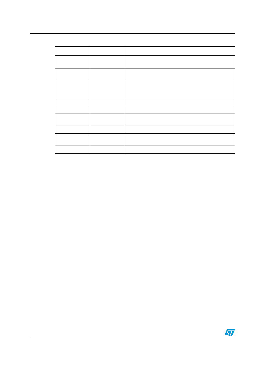
OCy
External
Output compare: TIMxCy when used as an output. Same as
OCyREF but includes possible polarity inversion.
OCyREF
Internal
Output compare reference: always active high, but may be
inverted to produce OCy.
PCLK
External
Peripheral clock connects to CK_INT and used to clock input
filtering. Its frequency is 12MHz if using the 24MHz crystal
oscillator and 6Mhz if using the 12MHz RC oscillator.
TIy
Internal
Timer input: TIMxCy when used as a timer input.
TIyFPy
Internal
Timer input after filtering and polarity selection.
TIMxCy
Internal
Timer channel at a GPIO pin: can be a capture input (ICy) or
a compare output (OCy).
TIMxCLK
External
Clock input (if selected) to the external trigger signal (ETR).
TIMxMSK
External
Clock mask (if enabled) AND'ed with the other timer's
TIMxCLK signal.
TRGI
Internal
Trigger input for slave mode controller.
Table 26.
Timer signal descriptions (continued)
Signal
Internal/external
Description
相关PDF资料 |
PDF描述 |
|---|---|
| STP506C-2IW-012V | SINGLE COLOR DISPLAY CLUSTER, WHITE, 152.4 mm |
| SUGR47M | DUAL COLOR LED, RED/GREEN, 5 mm |
| SUR76D | SINGLE COLOR LED, RED, 3 mm |
| SUY17D | SINGLE COLOR LED, YELLOW, 3.9 mm |
| SY405T | SINGLE COLOR LED, AMBER, 2.7 mm |
相关代理商/技术参数 |
参数描述 |
|---|---|
| STM32WC-RFCKIT | 功能描述:Zigbee/802.15.4开发工具 STM32W Low-Cost RF STM32F103 MCU Kit RoHS:否 制造商:Silicon Labs 产品:Development Kits 工具用于评估:EM35x 频率:2.4 GHz 接口类型:USB 工作电源电压: |
| STM32W-RFCKIT | 功能描述:开发板和工具包 - 无线 STM32W RF CNTRL KIT STM32F103 USB JTAG RoHS:否 制造商:Arduino 产品:Evaluation Boards 工具用于评估:AT32UC3L 核心:AVR32 频率: 接口类型:USB 工作电源电压:5 V |
| STM3-3 | 制造商:RINO MECH.(GENGARELL 功能描述: |
| STM330 | 制造商:EnOcean GmbH 功能描述:Temperature energy harvester, 868MHz |
| STM330U | 制造商:EnOcean GmbH 功能描述:Temperature energy harvester, 315MHz 制造商:EnOcean GmbH 功能描述:Temperature energy harvester, 902MHz |
发布紧急采购,3分钟左右您将得到回复。