参数资料
| 型号: | TC835CBU |
| 厂商: | Microchip Technology |
| 文件页数: | 13/26页 |
| 文件大小: | 0K |
| 描述: | IC ADC 4 1/2DGT BCD 64-MQFP |
| 标准包装: | 84 |
| 显示器类型: | LED |
| 配置: | 7 段显示 |
| 接口: | BCD |
| 数字或字符: | A/D,4.5 位数字 |
| 电流 - 电源: | 1mA |
| 电源电压: | 4 V ~ 6 V |
| 工作温度: | 0°C ~ 70°C |
| 安装类型: | 表面贴装 |
| 封装/外壳: | 64-BQFP |
| 供应商设备封装: | 64-PQFP(14x14) |
| 包装: | 管件 |
�� �
�
�TC835�
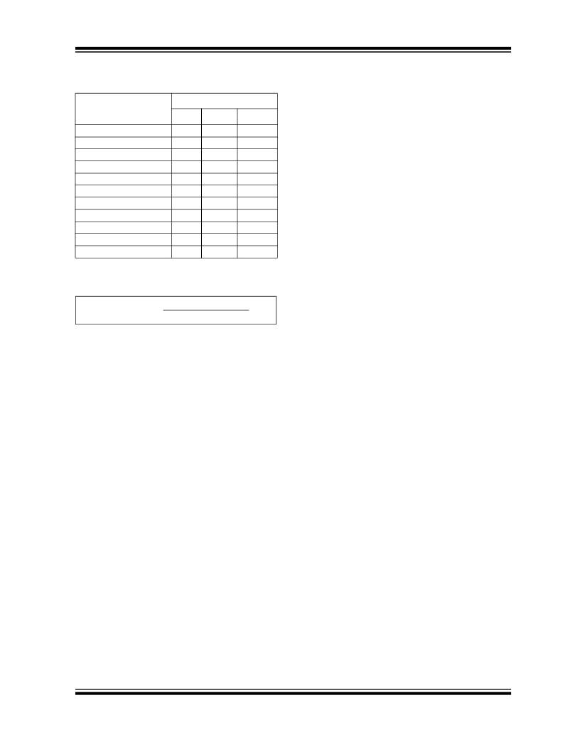
�TABLE� 6-2:�
�LINE� FREQUENCY� VS.�
�CLOCK� FREQUENCY�
�clock� frequency,� the� extra� count� or� counts� caused� by�
�comparator� delay� will� be� a� constant� and� can� be�
�subtracted� out� digitally.�
�Oscillator� Frequency�
�Line� Frequency� Rejection�
�The� clock� frequency� may� be� extended� above� 200� kHz�
�(kHz)�
�50.000�
�53.333�
�66.667�
�80.000�
�83.333�
�100.000�
�125.000�
�133.333�
�166.667�
�200.000�
�60Hz�
�?�
�—�
�?�
�—�
�—�
�?�
�—�
�—�
�—�
�?�
�50Hz�
�?�
�—�
�—�
�—�
�?�
�?�
�?�
�—�
�—�
�—�
�400Hz�
�?�
�?�
�?�
�?�
�?�
�?�
�?�
�?�
�?�
�?�
�without� this� error,� however,� by� using� a� low-value�
�resistor� in� series� with� the� integrating� capacitor.� The�
�effect� of� the� resistor� is� to� introduce� a� small� pedestal�
�voltage� onto� the� integrator� output� at� the� beginning� of�
�the� reference� integrate� phase.� By� careful� selection� of�
�the� ratio� between� this� resistor� and� the� integrating�
�resistor� (a� few� tens� of� ohms� in� the� recommended�
�circuit),� the� comparator� delay� can� be� compensated� and�
�the� maximum� clock� frequency� extended� by� approxi-�
�mately� a� factor� of� 3.� At� higher� frequencies,� ringing� and�
�second-order� breaks� will� cause� significant� nonlineari-�
�ties� in� the� first� few� counts� of� the� instrument.�
�The� minimum� clock� frequency� is� established� by� leak-�
�250.000�
�The� conversion� rate� is� easily� calculated:�
�age� on� the� auto� zero� and� reference� capacitors.� With�
�most� devices,� measurement� cycles� as� long� as� 10� sec-�
�onds� give� no� measurable� leakage� error.�
�EQUATION� 6-3:�
�Reading� 1/sec� =�
�Clock� Frequency� (Hz)�
�4000�
�The� clock� used� should� be� free� from� significant� phase� or�
�frequency� jitter.� Several� suitable� low-cost� oscillators�
��Typical� Applications.� The� multiplexed� output� means�
�that� if� the� display� takes� significant� current� from� the� logic�
�6.3�
�Power� Supplies� and� Grounds�
�supply,� the� clock� should� have� good� PSRR.�
�6.3.1�
�POWER� SUPPLIES�
�6.5�
�Zero� Crossing� Flip-Flop�
�The� TC835� is� designed� to� work� from� ±5V� supplies.� For�
�single� +5V� operation,� a� ICL7135� can� provide� a� –5V�
�supply.�
�The� flip� flop� interrogates� the� data� once� every� clock�
�pulse� after� the� transients� of� the� previous� clock� pulse�
�and� half-clock� pulse� have� died� down.� False� zero� cross-�
�ings� caused� by� clock� pulses� are� not� recognized.� Of�
�6.3.2�
�GROUNDING�
�course,� the� flip� flop� delays� the� true� zero� crossing� by� up�
�Systems� should� use� separate� digital� and� analog�
�ground� systems� to� avoid� loss� of� accuracy.�
�to� one� count� in� every� instance.� If� a� correction� were� not�
�made,� the� display� would� always� be� one� count� too� high.�
�Therefore,� the� counter� is� disabled� for� one� clock� pulse�
�6.4�
�High-Speed� Operation�
�at� the� beginning� of� the� reference� integrate� (de-inte-�
�The� maximum� conversion� rate� of� most� dual-slope� A/D�
�converters� is� limited� by� the� frequency� response� of� the�
�comparator.� The� comparator� in� this� circuit� follows� the�
�integrator� ramp� with� a� 3� μs� delay,� and� at� a� clock�
�frequency� of� 200� kHz� (5� μs� period),� half� of� the� first�
�reference� integrate� clock� period� is� lost� in� delay.� This�
�means� that� the� meter� reading� will� change� from� 0� to� 1�
�with� a� 50� μV� input,� 1� to� 2� with� 150� μV,� 2� to� 3� at� 250� μV,�
�etc.� This� transition� at� midpoint� is� considered� desirable�
�by� most� users,� however,� if� the� clock� frequency� is�
�increased� appreciably� above� 200� kHz,� the� instrument�
�will� flash� "� 1� "� on� noise� peaks� even� when� the� input� is�
�shorted.�
�For� many� dedicated� applications� where� the� input� signal�
�is� always� of� one� polarity,� the� delay� of� the� comparator�
�need� not� be� a� limitation.� Since� the� nonlinearity� and�
�noise� do� not� increase� substantially� with� frequency,�
�clock� rates� of� up� to� ~1� MHz� may� be� used.� For� a� fixed�
�?� 2007� Microchip� Technology� Inc.�
�grate)� phase.� This� one-count� delay� compensates� for�
�the� delay� of� the� zero� crossing� flip� flop� and� allows� the�
�correct� number� to� be� latched� into� the� display.� Similarly,�
�a� one-count� delay� at� the� beginning� of� auto� zero� gives�
�an� overload� display� of� 0000� instead� of� 0001.� No� delay�
�occurs� during� signal� integrate,� so� that� true� ratiometric�
�readings� result.�
�DS21478C-page� 13�
�相关PDF资料 |
PDF描述 |
|---|---|
| TC962IJA | IC REG SWITCHD CAP INV ADJ 8CDIP |
| TCM680COA | IC REG SWITCHD CAP DBL INV 8SOIC |
| TCM810LVNB713 | IC RESET MONITOR 4.63V SOT23B-3 |
| TCM811FERCTR | IC RESET MONITOR 1.75V SOT143-4 |
| TCM829ECT713 | IC REG MULTI CONFIG ADJ SOT23A-5 |
相关代理商/技术参数 |
参数描述 |
|---|---|
| TC835CBU713 | 功能描述:LED显示驱动器 4.5 D BCD A/D-PC Dat RoHS:否 制造商:Micrel 数位数量:5 片段数量: 安装风格:SMD/SMT 封装 / 箱体:PLCC-44 工作电源电压:4.75 V to 11 V 最大电源电流:10 mA 最大工作温度:+ 85 C 最小工作温度:- 40 C 封装:Tube |
| TC835CKW | 功能描述:LED显示驱动器 4.5 D BCD A/D-PC Dat RoHS:否 制造商:Micrel 数位数量:5 片段数量: 安装风格:SMD/SMT 封装 / 箱体:PLCC-44 工作电源电压:4.75 V to 11 V 最大电源电流:10 mA 最大工作温度:+ 85 C 最小工作温度:- 40 C 封装:Tube |
| TC835CKW713 | 功能描述:LED显示驱动器 4.5 D BCD A/D-PC Dat RoHS:否 制造商:Micrel 数位数量:5 片段数量: 安装风格:SMD/SMT 封装 / 箱体:PLCC-44 工作电源电压:4.75 V to 11 V 最大电源电流:10 mA 最大工作温度:+ 85 C 最小工作温度:- 40 C 封装:Tube |
| TC835CPI | 功能描述:LED显示驱动器 4.5 D BCD A/D-PC Dat RoHS:否 制造商:Micrel 数位数量:5 片段数量: 安装风格:SMD/SMT 封装 / 箱体:PLCC-44 工作电源电压:4.75 V to 11 V 最大电源电流:10 mA 最大工作温度:+ 85 C 最小工作温度:- 40 C 封装:Tube |
| TC8395-90 | 制造商:未知厂家 制造商全称:未知厂家 功能描述:16-Bit Microcontroller |
发布紧急采购,3分钟左右您将得到回复。