参数资料
| 型号: | TISP61089BGDR-S |
| 厂商: | Bourns Inc. |
| 文件页数: | 18/20页 |
| 文件大小: | 0K |
| 描述: | PROTECTOR PROGRAMMABLE SLIC |
| 标准包装: | 2,500 |
| 电压 - 击穿: | 64V |
| 电压 - 断路: | 170V |
| 电流 - 峰值脉冲(10 x 1000µs): | 30A |
| 电流 - 保持 (Ih): | 150mA |
| 元件数: | 2 |
| 电容: | 100pF |
| 封装/外壳: | 8-SOIC(0.154",3.90mm 宽) |
| 包装: | 带卷 (TR) |
�� �
�
�TISP61089B� High� Voltage� Ringing� SLIC� Protector�
�Overcurrent� and� Overvoltage� Protection� Coordination� (Continued)�
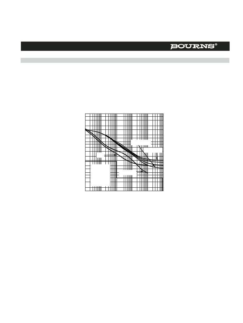
�The� overcurrent� protector� should� not� allow� current-time� durations� greater� than� the� TISP61089B� current� ratings,� otherwise� the� TISP61089B�
�may� fail.� A� satisfactory� fusible� resistor� performance� is� shown� in� Figure� 20.� The� line� feed� resistor� (LFR)� current-time� curve� is� above� the� first-level�
�currents� and� below� the� TISP61089B� rated� current� for� V� GG� >� -100� V.� This� particular� curve� is� for� a� Bourns� 4B04B-523-400� 2� x� 40� ?� ,� 2� %�
�tolerance,� 0.5� %� matched� resistor� module.� Fusible� resistors� are� also� available� with� integrated� thermal� fuses� or� PTC� thermistors.� Thermal� fuses�
�will� cause� a� rapid� drop� in� the� operating� current� after� about� 10� s.� Figure� 20� shows� the� fused� LFR� curve� for� a� Bourns� 4B04B-524-400� 2� x� 40� ?� ,�
�2� %� tolerance,� 0.5� %� matched� resistor� module� with� integrated� thermal� fuse� links.� The� Bourns� 4B04B-524-400� allows� the� TISP61089B� to�
�operate� down� to� its� full� rated� voltage� of� V� GG� =� -155� V.� An� LFR� with� integrated� PTC� thermistors� will� give� an� automatically� resettable� current�
�limiting� function� for� all� but� the� highest� currents.�
�PEAK� AC�
�vs�
�50�
�40�
�30�
�20�
�15�
�10�
�8�
�CURRENT� DURATION�
�AI6XDKA�
�6�
�5�
�4�
�3�
�2�
�1.5�
�1�
�0.8�
�LFR�
�First� Level�
�V� GG� =� -120� V�
�V� GG� =� -60� V�
�0.6�
�0.5�
�0.4�
�0.3�
�0.2�
�0.15�
�Tests� #� 1�
�through� 5,�
�25� ?� &� 40� ?�
�Fused� LFR�
�0.01�
�0.1�
�1� 10� 100�
�1000�
�t� —� Current� Duration� —� s�
�Figure� 20.� Line� Feed� Resistor� -� with� and� without� Thermal� Fuse�
�Ceramic� PTC� thermistors� are� available� in� suitable� ohmic� values� to� be� used� as� the� series� line� feed� resistor� R� S� .� Figure� 21� overlays� a� typical�
�ceramic� PTC� thermistor� operating� characteristic.� Some� of� the� first-level� tests� will� cause� thermistor� operation.� Generally,� the� resistance�
�matching� stability� of� the� two� PTC� thermistors� after� power� fault� switching� lightning� will� meet� the� required� line� balance� performance.�
�Ceramic� PTC� thermistors� reduce� in� resistance� value� under� high� voltage� conditions.� Under� high� current� impulse� conditions,� the� resistance� can�
�be� less� than� 50� %� of� the� d.c.� resistance.� This� means� that� more� current� than� expected� will� flow� under� high� voltage� impulse� conditions.� The�
�manufacturer� should� be� consulted� on� the� 2/10� currents� conducted� by� their� product� under� ‘1089� conditions.� To� keep� the� 2/10� current� below�
�120� A,� an� increase� of� the� PTC� thermistor� d.c.� resistance� value� to� 50� ?� or� more� may� be� needed.� In� controlled� temperature� environments,� where�
�the� temperature� does� not� drop� below� freezing,� the� TISP61089B� 2/10� capability� is� about� 170� A,� and� this� would� allow� a� lower� value� of�
�resistance.�
�Generally,� polymer� PTC� thermistors� are� not� available� in� sufficiently� high� ohmic� values� to� be� used� as� the� only� line� feed� resistance.� To� meet� the�
�required� resistance� value,� an� addition� (fixed)� series� resistance� can� be� used.� Figure� 22� overlays� a� typical� polymer� PTC� thermistor� operating�
�characteristic.� Compared� to� ceramic� PTC� thermistors,� the� lower� thermal� mass� of� the� polymer� type� will� generally� give� a� faster� current� reduction�
�time� than� the� ceramic� type.� However,� in� this� case� the� polymer� resistance� value� is� much� less� than� the� ceramic� value.� For� the� same� current� level,�
�the� dissipation� in� the� polymer� thermistor� is� much� less� than� the� ceramic� thermistor.� As� a� result,� the� polymer� thermistor� is� slower� to� operate� than�
�the� ceramic� one.�
�The� resistance� stability� of� polymer� PTC� thermistors� is� not� as� good� as� ceramic� ones.� However,� the� thermistor� resistance� change� will� be� diluted�
�by� additional� series� resistance.� If� an� SLIC� with� adaptive� line� balance� is� used,� thermistor� resistance� stability� may� not� be� a� problem.� Polymer�
�PTC� thermistors� do� not� have� a� resistance� decrease� under� high� voltage� conditions.�
�OCTOBER� 2000� -� REVISED� JULY� 2008�
�Specifications� are� subject� to� change� without� notice.�
�Customers� should� verify� actual� device� performance� in� their� specific� applications.�
�相关PDF资料 |
PDF描述 |
|---|---|
| 1-1586585-0 | CONN HEADER 10POS VERT 4.2MM TIN |
| 641216-3 | CONN HEADER RT/A .100 3POS 30AU |
| 103233-1 | CONN HDR 4POS A/PIN STR PCB |
| 929975-01-28-RK | CONN RECEPT .100 DUAL STR 56POS |
| 929850-01-30-10 | CONN RECEPT .100 SNGL STR 30POS |
相关代理商/技术参数 |
参数描述 |
|---|---|
| TISP61089BSDR-S | 功能描述:SCR PROTECTOR - QUAD PROGRAMMABLE RoHS:否 制造商:STMicroelectronics 最大转折电流 IBO:480 A 额定重复关闭状态电压 VDRM:600 V 关闭状态漏泄电流(在 VDRM IDRM 下):5 uA 开启状态 RMS 电流 (It RMS): 正向电压下降:1.6 V 栅触发电压 (Vgt):1.3 V 最大栅极峰值反向电压:5 V 栅触发电流 (Igt):35 mA 保持电流(Ih 最大值):75 mA 安装风格:Through Hole 封装 / 箱体:TO-220 封装:Tube |
| TISP61089D | 功能描述:SCR Dual P Gate Forward Conducting RoHS:否 制造商:STMicroelectronics 最大转折电流 IBO:480 A 额定重复关闭状态电压 VDRM:600 V 关闭状态漏泄电流(在 VDRM IDRM 下):5 uA 开启状态 RMS 电流 (It RMS): 正向电压下降:1.6 V 栅触发电压 (Vgt):1.3 V 最大栅极峰值反向电压:5 V 栅触发电流 (Igt):35 mA 保持电流(Ih 最大值):75 mA 安装风格:Through Hole 封装 / 箱体:TO-220 封装:Tube |
| TISP61089DR | 功能描述:SCR Dual P Gate Forward Conducting RoHS:否 制造商:STMicroelectronics 最大转折电流 IBO:480 A 额定重复关闭状态电压 VDRM:600 V 关闭状态漏泄电流(在 VDRM IDRM 下):5 uA 开启状态 RMS 电流 (It RMS): 正向电压下降:1.6 V 栅触发电压 (Vgt):1.3 V 最大栅极峰值反向电压:5 V 栅触发电流 (Igt):35 mA 保持电流(Ih 最大值):75 mA 安装风格:Through Hole 封装 / 箱体:TO-220 封装:Tube |
| TISP61089DR-S | 功能描述:SCR Dual P Gate Forward Conducting RoHS:否 制造商:STMicroelectronics 最大转折电流 IBO:480 A 额定重复关闭状态电压 VDRM:600 V 关闭状态漏泄电流(在 VDRM IDRM 下):5 uA 开启状态 RMS 电流 (It RMS): 正向电压下降:1.6 V 栅触发电压 (Vgt):1.3 V 最大栅极峰值反向电压:5 V 栅触发电流 (Igt):35 mA 保持电流(Ih 最大值):75 mA 安装风格:Through Hole 封装 / 箱体:TO-220 封装:Tube |
| TISP61089DS | 制造商:Bourns Inc 功能描述: |
发布紧急采购,3分钟左右您将得到回复。