- 您现在的位置:买卖IC网 > PDF目录373745 > TSS463A-TERZ (Atmel Corp.) VAN Data Link Controller with Serial Interface PDF资料下载
参数资料
| 型号: | TSS463A-TERZ |
| 厂商: | Atmel Corp. |
| 英文描述: | VAN Data Link Controller with Serial Interface |
| 中文描述: | 凡数据与串行接口链路控制器 |
| 文件页数: | 23/60页 |
| 文件大小: | 816K |
| 代理商: | TSS463A-TERZ |
第1页第2页第3页第4页第5页第6页第7页第8页第9页第10页第11页第12页第13页第14页第15页第16页第17页第18页第19页第20页第21页第22页当前第23页第24页第25页第26页第27页第28页第29页第30页第31页第32页第33页第34页第35页第36页第37页第38页第39页第40页第41页第42页第43页第44页第45页第46页第47页第48页第49页第50页第51页第52页第53页第54页第55页第56页第57页第58页第59页第60页
23
TSS463-AA
4205B–AUTO–12/04
Status bits give permanent information on the diagnosis performed, whatever the pro-
grammed operating mode. This is encoded over three bits: Sa, Sb and Sc.
Sa and Sb bits indicate the four possible states of the VAN bus.
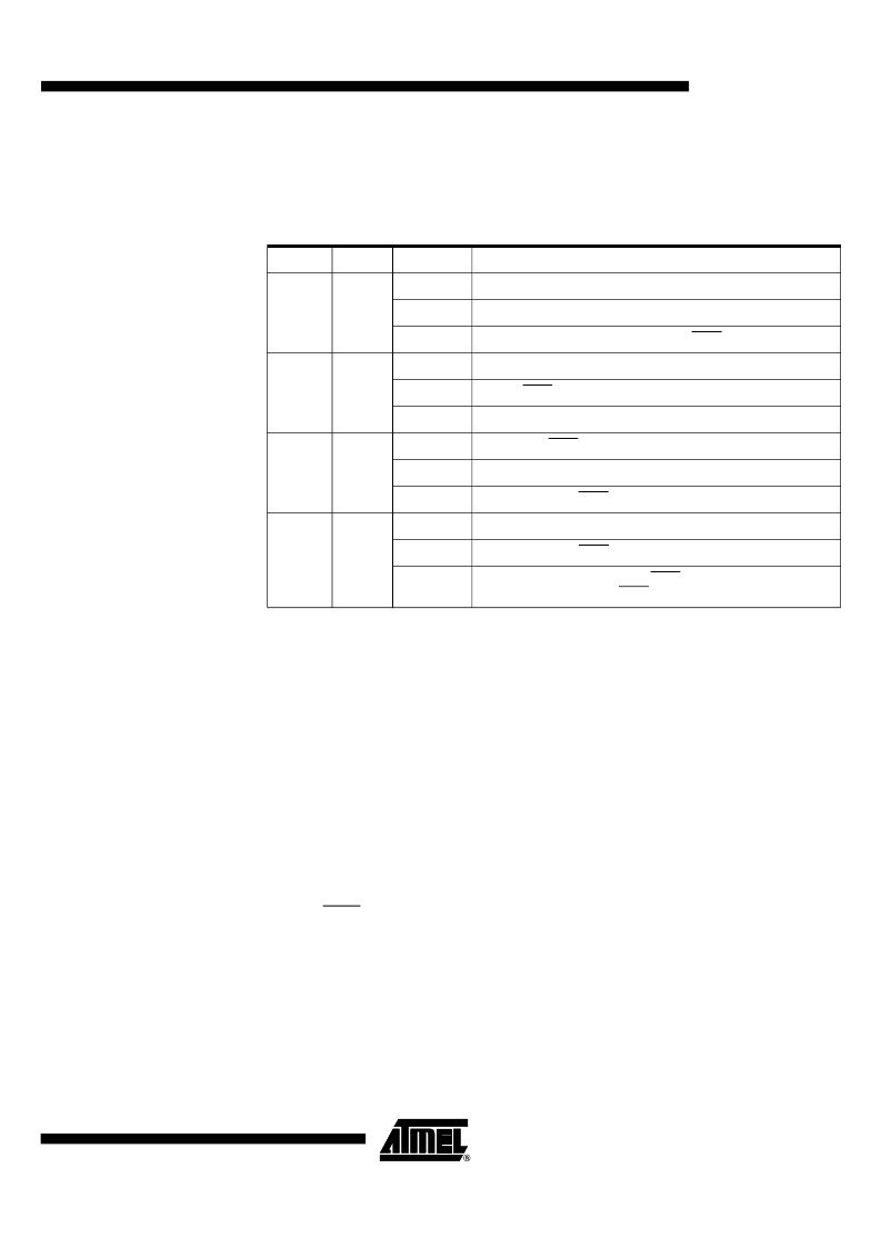
Table 3.
Status Bits: Sa and Sb
Sc: As soon as one of the three inputs (RXD2, RXD1, RXD0) differs from the others
in the input comparison analysis performed by the diagnosis system, Sc is set.
The only way to reset this status bit is through the RI signal or a general reset.
Internal Operations
Digital Filtering
If several spurious pulses occur during one bit, the diagnosis for defective conductor
may occur. To avoid such errors, digital filters are implemented.
Filtering operation is based on sampling of the comparator output signals. A transition is
taken into account only if it is observed over five samples (1/16
th
of timeslot).
Transition Analyses
These analyses are continuously done on the effective edges on comparators after digi-
tal filtering.
Asynchronous diagnosis
The asynchronous diagnosis is done by comparing the number of edges on DATA
and DATA.
If four edges are detected on one input and no edges on the other during the same
period, the second input is considered faulty and the diagnosis mode will change to
one of the degraded modes.
Synchronous diagnosis
The synchronous diagnosis counts the number of edges on the data input
connected to the reception logic during one SDC period.
If there are less than four edges during one SDC period, the diagnosis mode will
change to the major error mode.
Sa
Sb
Communication
0
0
Mode
Nominal
Fault
No fault on VAN bus
Status
Differential communication on DATA and DATA
0
1
Mode
Degraded on DATA
Fault
Fault on DATA
Status
Communication on DATA
1
0
Mode
Degraded on DATA
Fault
Fault on DATA
Status
Communication on DATA
1
1
Mode
Major error
Fault
Fault on DATA and DATA
Status
No communication on DATA and DATA (attempt to communicate
alternatively on DATA then DATA every SDC period)
相关PDF资料 |
PDF描述 |
|---|---|
| TSS463C | VAN Data Link Controller with Serial Interface |
| TSS4B02G | Single Phase 4.0 Amps. Glass Passivated Super Fast Bridge Rectifiers |
| TSS4B03G | Single Phase 4.0 Amps. Glass Passivated Super Fast Bridge Rectifiers |
| TSS4B01G | Single Phase 4.0 Amps. Glass Passivated Super Fast Bridge Rectifiers |
| TSS5G45S | TOSHIBA SOLID STATE AC RELAY |
相关代理商/技术参数 |
参数描述 |
|---|---|
| TSS463B | 制造商:ATMEL 制造商全称:ATMEL Corporation 功能描述:Serial VAN Data Link Controller |
| TSS463B_03 | 制造商:ATMEL 制造商全称:ATMEL Corporation 功能描述:Serial VAN Data Link Controller |
| TSS463B_04 | 制造商:ATMEL 制造商全称:ATMEL Corporation 功能描述:VAN Data Link Controller with Serial Interface |
| TSS463B-TERA | 制造商:Temic 功能描述:LAN Node Controller, 16 Pin, SOP |
| TSS463B-TERA-9 | 制造商:ATMEL 制造商全称:ATMEL Corporation 功能描述:VAN Data Link Controller with Serial Interface |
发布紧急采购,3分钟左右您将得到回复。