- 您现在的位置:买卖IC网 > PDF目录68459 > W6692ACD (WINBOND ELECTRONICS CORP) DATACOM, ISDN CONTROLLER, PQFP100 PDF资料下载
参数资料
| 型号: | W6692ACD |
| 厂商: | WINBOND ELECTRONICS CORP |
| 元件分类: | 数字传输电路 |
| 英文描述: | DATACOM, ISDN CONTROLLER, PQFP100 |
| 封装: | LQFP-100 |
| 文件页数: | 52/98页 |
| 文件大小: | 584K |
| 代理商: | W6692ACD |
第1页第2页第3页第4页第5页第6页第7页第8页第9页第10页第11页第12页第13页第14页第15页第16页第17页第18页第19页第20页第21页第22页第23页第24页第25页第26页第27页第28页第29页第30页第31页第32页第33页第34页第35页第36页第37页第38页第39页第40页第41页第42页第43页第44页第45页第46页第47页第48页第49页第50页第51页当前第52页第53页第54页第55页第56页第57页第58页第59页第60页第61页第62页第63页第64页第65页第66页第67页第68页第69页第70页第71页第72页第73页第74页第75页第76页第77页第78页第79页第80页第81页第82页第83页第84页第85页第86页第87页第88页第89页第90页第91页第92页第93页第94页第95页第96页第97页第98页
Data Sheet
W6692A PCI ISDN S/T-Controller
Publication Release Date:
Mar,2000
Revision 1.0
-56 -
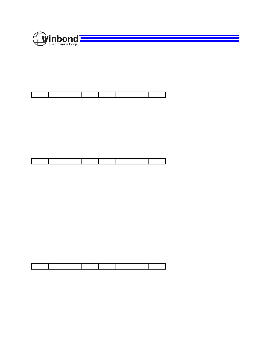
8.1.17 D_ch TEI2 Register D_TEI2
Read/Write
Address 40H/10H
Value after reset: 00H
7
6
5
4
3
2
1
0
TA27
TA26
TA25
TA24
TA23
TA22
TA21
TA20
TA27 - TA20
This register contains the second choice of the second byte address of received frame. For LAPD frame, TA27 - TA21 is the
TEI value, TA20 is EA = 1.
8.1.18 D_ch Receive Frame Byte Count High
D_RBCH
Read Address 44H/11H
Value after reset: 40H
7
6
5
4
3
2
1
0
VN1
VN0
LOV
RBC12
RBC11
RBC10
RBC9
RBC8
VN1-0
Chip Version Number
This is the chip version number. It is read as 01B.
LOV
Length Overflow
A "1" in this bit indicates
≥ 8192 bytes are received and the frame is not yet complete. This bit is valid only after an D_RME
interrupt and remains valid until the frame is acknowledge via the RACK command.
RBC12-8
Receive Byte Count
Four most significant bits of the total frame length. These bits are valid only after an D_RME interrupt and remain valid until the
frame is acknowledge via the RACK command.
8.1.19 D_ch Receive Frame Byte Count Low
D_RBCL
Read
Address 48H/12H
Value after reset: 00H
7
6
5
4
3
2
1
0
RBC7
RBC6
RBC5
RBC4
RBC3
RBC2
RBC1
RBC0
RBC7-0
Receive Byte Count
Eight least significant bits of the total frame length. Bits RBC5-0 also indicate the length of the data currently available in
D_RFIFO. These bits are valid only after an D_RME interrupt and remain valid until the frame is acknowledged via the RACK
command.
相关PDF资料 |
PDF描述 |
|---|---|
| W6692ACF | DATACOM, ISDN CONTROLLER, PQFP100 |
| W6694ACD | DATACOM, ISDN CONTROLLER, PQFP48 |
| W671320P | TELECOM-SLIC, PQCC28 |
| W671361P | TELECOM-SLIC, PQCC28 |
| W671361Y | TELECOM-SLIC, QCC32 |
相关代理商/技术参数 |
参数描述 |
|---|---|
| W6692ACF | 制造商:未知厂家 制造商全称:未知厂家 功能描述:ISDN LINE INTERFACE|BASIC|CMOS|QFP|100PIN|PLASTIC |
| W6694 | 制造商:WINBOND 制造商全称:Winbond 功能描述:USB Bus ISDN S/T-Controller |
| W6694A | 制造商:未知厂家 制造商全称:未知厂家 功能描述:TE Mode S/T Controller with USB 1.1 Interface |
| W6694CD | 制造商:WINBOND 制造商全称:Winbond 功能描述:USB Bus ISDN S/T-Controller |
| W66ARX-18 | 制造商:Magnecraft 功能描述: |
发布紧急采购,3分钟左右您将得到回复。