参数资料
| 型号: | XE8805AMI028LF |
| 厂商: | Semtech |
| 文件页数: | 53/156页 |
| 文件大小: | 0K |
| 描述: | IC DAS 16BIT FLASH 8K MTP 64LQFP |
| 标准包装: | 160 |
| 系列: | XE880x |
| 应用: | 感测机 |
| 核心处理器: | Coolrisc816? |
| 程序存储器类型: | 闪存(22 kB) |
| 控制器系列: | XE8000 |
| RAM 容量: | 512 x 8 |
| 接口: | UART,USRT |
| 输入/输出数: | 24 |
| 电源电压: | 2.4 V ~ 5.5 V |
| 工作温度: | -40°C ~ 85°C |
| 安装类型: | 表面贴装 |
| 封装/外壳: | 64-LQFP |
| 包装: | 托盘 |
| 供应商设备封装: | 64-LQFP(10x10) |
| 产品目录页面: | 585 (CN2011-ZH PDF) |
| 配用: | XE8000MP-ND - PROG BOARD AND PROSTART2 CARD |
第1页第2页第3页第4页第5页第6页第7页第8页第9页第10页第11页第12页第13页第14页第15页第16页第17页第18页第19页第20页第21页第22页第23页第24页第25页第26页第27页第28页第29页第30页第31页第32页第33页第34页第35页第36页第37页第38页第39页第40页第41页第42页第43页第44页第45页第46页第47页第48页第49页第50页第51页第52页当前第53页第54页第55页第56页第57页第58页第59页第60页第61页第62页第63页第64页第65页第66页第67页第68页第69页第70页第71页第72页第73页第74页第75页第76页第77页第78页第79页第80页第81页第82页第83页第84页第85页第86页第87页第88页第89页第90页第91页第92页第93页第94页第95页第96页第97页第98页第99页第100页第101页第102页第103页第104页第105页第106页第107页第108页第109页第110页第111页第112页第113页第114页第115页第116页第117页第118页第119页第120页第121页第122页第123页第124页第125页第126页第127页第128页第129页第130页第131页第132页第133页第134页第135页第136页第137页第138页第139页第140页第141页第142页第143页第144页第145页第146页第147页第148页第149页第150页第151页第152页第153页第154页第155页第156页
Semtech 2006
www.semtech.com
20-6
XE8805/05A
CascadeAB
CountPWM0
CapFunc(1:0)
Counter A
mode
Counter B
mode
IrqA
source
IrqB
source
PB(0)
function
0
00
Counter 8b
Downup: A
Counter 8b
Downup: B
Counter
A
Counter
B
PB(0)
1
0
00
Counter 16b AB
Downup: A
Counter
AB
-
PB(0)
0
1
00
PWM 8b
Down
Counter 8b
Down
-
Counter
B
PWM A
1
00
PWM 10 – 16b AB
Down
-
PWM AB
0
1x
or
x1
Captured
counter 8b
Downup: A
Captured
counter 8b
Downup: B
Capture
A
Capture
B
PB(0)
1
0
1x
or
x1
Captured counter 16b AB
Downup: A
Capture
AB
Capture
AB
PB(0)
0
1
1x
or
x1
PWM 8b
Down
Captured
counter 8b
Downup: B
Must not
be used
Capture
B
PWM A
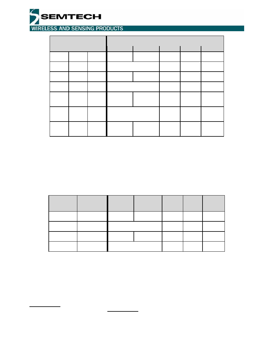
Table 20-11: Operating modes of the counters A and B
Table 20-12 shows the different operation modes of the counters C and D as a function of the mode control bits.
For all counter modes, the source of the down or upcount selection is given (either the bit CntCDownUp or the bit
CntDDownUp). The mapping of the interrupt sources IrqC and IrqD and the PWM output on PB(1) in these
different modes is also shown.
The switching between different modes must be done while the concerned counters are stopped. While switching
capture mode on and off, unwanted interrupts can appear on the interrupt channels concerned by this mode
change.
CascadeCD
CountPWM1
Counter C
mode
Counter D
mode
IrqC
Source
IrqD
source
PB(1)
function
0
Counter 8b
Downup: C
Counter 8b
Downup: D
Counter
C
Counter
D
PB(1)
1
0
Counter 16b CD
Downup: C
Counter
CD
-
PB(1)
0
1
PWM 8b
Down
Counter 8b
Down
-
Counter
D
PWM C
1
PWM 10 – 16b CD
Down
-
PWM CD
Table 20-12: Operating modes of the counters C and D
20.9
Counter / Timer mode
The counters in counter / timer mode are generally used to generate interrupts after a predefined number of clock
periods applied on the counter clock input.
Each counter can be set individually either in upcount mode by setting CntXDownUp in the register
RegCntConfig1 or in downcount mode by resetting this bit. Counters A and B can be cascaded to behave as a 16
bit counter by setting CascadeAB in the RegCntConfig1 register. Counters C and D can be cascaded by setting
CascadeCD. When cascaded, the up/down count modes of the counters B and D are defined respectively by the
up/down count modes set for the counters A and C.
Not
Recommended
for
New
Designs
相关PDF资料 |
PDF描述 |
|---|---|
| XE8807AMI026TLF | IC MCU LOW PWR MTP FLASH 32-TQFP |
| XIO2200AGGW | IC PCI-EXPRESS/BUS BRIDGE 176BGA |
| XIO2200AZGW | IC PCI-EXPRESS/BUS BRIDGE 176BGA |
| XPC823ZT81B2T | IC MPU POWERQUICC 81MHZ 256-PBGA |
| XPC8240RZU250E | MCU HOST PROCESSOR 352-TBGA |
相关代理商/技术参数 |
参数描述 |
|---|---|
| XE8805AMI028TLF | 制造商:Semtech Corporation 功能描述: |
| XE8805MI028 | 制造商:SEMTECH 制造商全称:Semtech Corporation 功能描述:Data Acquisition MCU |
| XE8806A | 制造商:SEMTECH 制造商全称:Semtech Corporation 功能描述:Ultra Low-Power Low-Voltage |
| XE8806AMI000 | 制造商:SEMTECH 制造商全称:Semtech Corporation 功能描述:Ultra Low-Power Low-Voltage |
| XE8806AMI026LF | 制造商:SEMTECH 制造商全称:Semtech Corporation 功能描述:Ultra Low-Power Low-Voltage |
发布紧急采购,3分钟左右您将得到回复。