- 您现在的位置:买卖IC网 > Datasheet目录279 > 101-1109 (Rabbit Semiconductor)KIT EMBEDDED PLC APPLICATION Datasheet资料下载
参数资料
| 型号: | 101-1109 |
| 厂商: | Rabbit Semiconductor |
| 文件页数: | 32/70页 |
| 文件大小: | 0K |
| 描述: | KIT EMBEDDED PLC APPLICATION |
| 标准包装: | 1 |
| 系列: | Coyote™ |
| 类型: | MPU 模块 |
| 适用于相关产品: | BL2500 |
| 所含物品: | BL2500、ISaGRAF V3.50、嵌入式 PLC 软件内核、ISaGRAF 编程缆线和说明文档 |
第1页第2页第3页第4页第5页第6页第7页第8页第9页第10页第11页第12页第13页第14页第15页第16页第17页第18页第19页第20页第21页第22页第23页第24页第25页第26页第27页第28页第29页第30页第31页当前第32页第33页第34页第35页第36页第37页第38页第39页第40页第41页第42页第43页第44页第45页第46页第47页第48页第49页第50页第51页第52页第53页第54页第55页第56页第57页第58页第59页第60页第61页第62页第63页第64页第65页第66页第67页第68页第69页第70页
�� �
�
�EMBEDDED�
�PLC� BL2500� User’s� Manual�
�Running� Sample� Applications�
�6.� Follow� Steps� 6� to� 11� in� Section� 3.4.1� to� create� and� populate� the� application’s� Dictionary� with� SW1�
�and� SW2� Boolean� input� variables� (connected� to� Channel� 1� and� 2� of� the� bl25di� I/O� board�
�respectively);� and� LED1� Boolean� output� variable� connected� to� Channel� 1� of� the� bl25led� I/O� board.�
�7.� On� the� B25TEST2� –� Programs� window� double-click� on� LDtest1� program.� The� Quick� Ladder�
�Diagram� Editor� contains� an� editing� grid,� a� logical� matrix� where� each� cell� of� the� matrix� may� contain�
�up� to� one� LD� symbol.� Press� F2:� Contact� on� the� left� button�
�on� the� toolbar� to� insert� a� new�
�rung� .� A� new� rung� with� one� contact� and� one� coil� is� created.�
�8.� Double� click� the� rung� comment� (*� *)� cell� to� insert� a� comment� such� as� (*Exclusive� OR� logic� for�
�switching� on� LED*).�
�9.� Double� click� the� contact�
�on� the� rung� and� select� SW1� for� an� input.�
�10.� With� the� SW1� contact� selected,� press� F3:� Contact� on� the� right� button�
�on� the� toolbar.�
�11.� Double� click� the� new� contact� and� select� SW2� variable.� Click� once� on� the� Coil/contact� type� button�
�to� negate� this� contact.�
�12.� Select� the� Select� button�
�on� the� toolbar.� Select� both� contacts� on� the� rung� by� clicking� on� one�
�contact� and� dragging� the� mouse� over� to� the� next� contact� before� releasing� the� mouse� button.� Press�
�F4:� Parallel� contact� button�
�to� create� two� new� contacts� in� parallel� with� the� selected� contacts.�
�13.� Repeat� steps� 9� and� 11� except� negate� the� SW1� contact� with� the� Coil/contact� type� button� this� time�
�instead� of� the� SW2� contact.�
�14.� Double� click� on� the� coil�
�on� the� rung� and� select� LED1� for� an� output.�
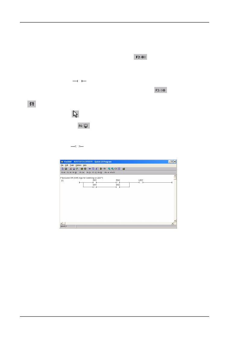
�15.� The� LDtest1� program� should� now� appear� as� follows:�
�16.� Save� the� program� by� selecting� File� menu� →� Save� .� Press� OK� button� on� the� Update� diary� window.�
�Close� the� LDtest1� –� QuickLD� Program� window.�
�17.� Follow� Steps� 17� to� 25� in� Section� 3.4.1� to� compile� the� application� and� download� it� to� the� Target� PLC.�
�18.� Double-click� on� LDtest1� program.� The� LDTEST1� –� Quick� LD� Programs� window� is� displayed� with�
�the� variables� in� BLUE� or� RED� colour� depending� on� its� current� state,� FALSE� or� TRUE� respectively.�
�Press� the� SW1� (short-circuit� digital� input� IN00)� and� the� LED1� will� be� turned� ON� as� well� as� the� state� of�
�LED1� in� the� Programs� window� will� change.� The� PLC� program� implements� a� Boolean� XOR� operation�
�on� SW1� and� SW2� with� the� result� set� on� the� LED1.�
�OEM� Technology� Solutions�
�Page� 26�
�相关PDF资料 |
PDF描述 |
|---|---|
| 101-1147 | KIT RIO PROGRAM I/O |
| 101-606 | CONN SOCKET IDC 60POS W/KEY GOLD |
| 10113616-01531LF | CONN MOD JACK 8PORT 8/8 R/A PCB |
| 10117863-5036010LF | CONN MOD JACK 8/8 R/A PCB |
| 10118061-5005010LF | CONN MOD JACK 2PORT 8/8 R/A PCB |
相关代理商/技术参数 |
参数描述 |
|---|---|
| 10-1110B | 制造商:Datak Corporation 功能描述: |
| 101110F9012M440ZA | 制造商:SUYIN-USA 制造商全称:SUYIN-USA 功能描述:RJ45 1X1 TAB DOWN W/LED & TRANSFORMER |
| 101110F9017M447ZA | 制造商:SUYIN-USA 制造商全称:SUYIN-USA 功能描述:RJ45 1X1 TAB DOWN W/LED & TRANSFORMER |
| 101110F9042M442ZA | 制造商:SUYIN-USA 制造商全称:SUYIN-USA 功能描述:RJ45 1X1 TAP DOWN W/LED & TRANSFORMER |
| 101110F9082M446ZA | 制造商:SUYIN-USA 制造商全称:SUYIN-USA 功能描述:RJ45 1X1 TAB DOWN W/LED & TRANSFORMER |
发布紧急采购,3分钟左右您将得到回复。