- 您现在的位置:买卖IC网 > PDF目录157280 > 5962R9855201VYC 32-BIT, 12 MHz, RISC MICROCONTROLLER, CQFP132 PDF资料下载
参数资料
| 型号: | 5962R9855201VYC |
| 元件分类: | 微控制器/微处理器 |
| 英文描述: | 32-BIT, 12 MHz, RISC MICROCONTROLLER, CQFP132 |
| 封装: | QFP-132 |
| 文件页数: | 35/64页 |
| 文件大小: | 1464K |
| 代理商: | 5962R9855201VYC |
第1页第2页第3页第4页第5页第6页第7页第8页第9页第10页第11页第12页第13页第14页第15页第16页第17页第18页第19页第20页第21页第22页第23页第24页第25页第26页第27页第28页第29页第30页第31页第32页第33页第34页当前第35页第36页第37页第38页第39页第40页第41页第42页第43页第44页第45页第46页第47页第48页第49页第50页第51页第52页第53页第54页第55页第56页第57页第58页第59页第60页第61页第62页第63页第64页
40
118
D2
TTO
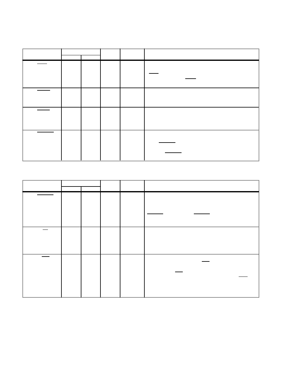
OPERAND DATA BUS ARBITRATION
PIN NAME
PIN NUMBER
FLTPK
PGA
TYPE
ACTIVE
DESCRIPTION
119
120
E3
C1
TUI
Bus Request. The UT69R000 asserts this signal to indicate
it is requesting control of the Operand data bus (D0 - D15).
BRQ enters a high-impedance state when the UT69R000
is in the test mode (TEST = 0).
Bus Grant. When asserted, this signal indicates the
UT69R000 may take control of the Operand data bus. It is
tied to an internal pull-up resistor.
Bus Busy. A bus master asserts this input to inform the
UT69R000 that another bus master is using the Operand
data bus. It is tied to an internal pull-up resistor.
OPERAND DATA BUS CONTROL
PIN NAME
PIN NUMBER
FLTPK
PGA
TYPE
ACTIVE
DESCRIPTION
121
112
E2
B3
TUI
TTO
Data Transfer Acknowledge. This signal tells the
UT69R000 that a data transfer has been acknowledged
and the UT69R000 can complete the bus cycle. To
assure the UT69R000 operates with no wait states,
DTACK can be tied low. DTACK is tied to an internal
pull-up resistor.
Memory or I/O. Indicates whether the current bus cycle
is for memory (high) or I/O (low). It remains in the high-
impedance state during bus cycles when the UT69R000
does not control the Operand buses.
AL
117
B1
TTO
AL
Bus Grant Acknowledge Output. The UT69R000 asserts
this signal to indicate it is the current bus master. When
low, BGACK inhibits other devices from becoming the
bus master. When the UT69R000 relinquishes control of
the bus, BGACK enters a high-impedance state.
114
C4
TTO
Read/Write. Indicates the direction of data flow with
respect to the UT69R000. R/WR high means the
UT69R000 is attempting to read data from an external
device, and R/WR low means the UT69R000 is
attempting to write data to an external device. R/WR
remains in a high-impedance state when the UT69R000
does not control the Operand buses.
Continued on page 41.
--
BRQ
BGNT
BUSY
BGACK
DTACK
M/IO
R/WR
相关PDF资料 |
PDF描述 |
|---|---|
| 5962R9855202QYC | 32-BIT, 16 MHz, RISC MICROCONTROLLER, CQFP132 |
| 5962R9855202VZA | 32-BIT, 16 MHz, RISC MICROCONTROLLER, CQFP132 |
| 5962F9651601VCX | AC SERIES, HEX 1-INPUT INVERT GATE, CDIP14 |
| 5962F9651601VXX | AC SERIES, HEX 1-INPUT INVERT GATE, CDFP14 |
| 5962F9654501VXC | ACT SERIES, OTHER DECODER/DRIVER, INVERTED OUTPUT, CDFP16 |
相关代理商/技术参数 |
参数描述 |
|---|---|
| 5962R9863601VGA | 制造商:Analog Devices 功能描述: |
| 5962R9863602VGA | 制造商:Analog Devices 功能描述:OP AMP, JFET-INPUT - Rail/Tube |
| 5962R9863701VGA | 制造商:Analog Devices 功能描述:- Rail/Tube |
| 5962R9863701VHA | 制造商:Analog Devices 功能描述:AEROSPACE LOW INPUT CURRENT OPERATIONAL AMPLIFIER - Rail/Tube |
| 5962R9863701VPA | 制造商:Analog Devices 功能描述:OP AMP, GENERAL PURPOSE - Rail/Tube |
发布紧急采购,3分钟左右您将得到回复。