- 您现在的位置:买卖IC网 > PDF目录157280 > 5962R9855201VYC 32-BIT, 12 MHz, RISC MICROCONTROLLER, CQFP132 PDF资料下载
参数资料
| 型号: | 5962R9855201VYC |
| 元件分类: | 微控制器/微处理器 |
| 英文描述: | 32-BIT, 12 MHz, RISC MICROCONTROLLER, CQFP132 |
| 封装: | QFP-132 |
| 文件页数: | 63/64页 |
| 文件大小: | 1464K |
| 代理商: | 5962R9855201VYC |
第1页第2页第3页第4页第5页第6页第7页第8页第9页第10页第11页第12页第13页第14页第15页第16页第17页第18页第19页第20页第21页第22页第23页第24页第25页第26页第27页第28页第29页第30页第31页第32页第33页第34页第35页第36页第37页第38页第39页第40页第41页第42页第43页第44页第45页第46页第47页第48页第49页第50页第51页第52页第53页第54页第55页第56页第57页第58页第59页第60页第61页第62页当前第63页第64页
8
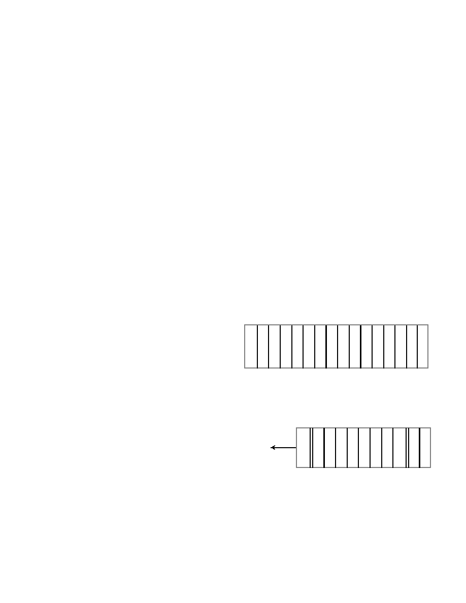
UART Receiver Register (RCVR)
The UART Receiver Buffer Register (see figure 7) receives
9600-baud asynchronous serial data through the UARTIN
input pin on the UT69R000. Each serial data string contains an
active-low Start bit, eight Data bits, an odd Parity bit, and an
active-high Stop bit. Figure 8 shows a single serial data string.
While receiving a serial data string, the UT69R000 generates
four status flags: Data Ready (DR), Overrun Error (OE),
Framing Error (FE), and Parity Error (PE). The UT69R000
stores these bits in the System Status Register.
Receiver buffer register bits 15-8 are always low. Bit numbers,
7 to 0 (RCD7 - RCD0) contain data the UT69R000 receives
via the serial data port. RCD7 is the MSB; RCD0 is the LSB.
Bit 5
FE
Framing Error. When active, this bit indicates a stop bit was
missing from the serial transmission string. Cleared on next
transmission. [0]
Bit 4
PE
Parity Error. When active, this bit indicates the serial
transmission was received with the incorrect parity. Cleared
on next transmission. [0]
Bit 3
CN
Discrete Input 2. This bit reflects the input stimulus applied
to the input pin.
Bit 2
TBE
UART Transmitter Buffer Empty. This bit indicates the
Transmitter Buffer Register is empty and ready for data. [0]
Bit 1
TE
UART Transmitter Empty. This bit is low while the UART is
transmitting data and goes high when the transmission is
complete. [0]
Bit 0
DR
UART Data Ready. This active-high signal indicates the
UART received a serial data word and this data is available.
Cleared on the execution of INR Rd, RCVR. [0]
Bit Number
Mnemonic
Description
15 14 13 12 11 10 9
8
7
5
4
3 2
1 0
05
04
03
02
01
00
7
06
0
6
R
C
D
R
C
D
R
C
D
R
C
D
R
C
D
R
C
D
R
C
D
R
C
D
MSB
LSB
Figure 7. The UART Receiver
Buffer Register (RCVR)
5
4
T3
R
2
01
S
T
D
7
R
C
D
R
C
D
R
C
6
R
C
D
R
C
D
R
C
D
R
C
D
R
C
D
P
A
S
T
O
Figure 8. UART Receiver Single Serial
Data String
P
R
DATA
FLOW
相关PDF资料 |
PDF描述 |
|---|---|
| 5962R9855202QYC | 32-BIT, 16 MHz, RISC MICROCONTROLLER, CQFP132 |
| 5962R9855202VZA | 32-BIT, 16 MHz, RISC MICROCONTROLLER, CQFP132 |
| 5962F9651601VCX | AC SERIES, HEX 1-INPUT INVERT GATE, CDIP14 |
| 5962F9651601VXX | AC SERIES, HEX 1-INPUT INVERT GATE, CDFP14 |
| 5962F9654501VXC | ACT SERIES, OTHER DECODER/DRIVER, INVERTED OUTPUT, CDFP16 |
相关代理商/技术参数 |
参数描述 |
|---|---|
| 5962R9863601VGA | 制造商:Analog Devices 功能描述: |
| 5962R9863602VGA | 制造商:Analog Devices 功能描述:OP AMP, JFET-INPUT - Rail/Tube |
| 5962R9863701VGA | 制造商:Analog Devices 功能描述:- Rail/Tube |
| 5962R9863701VHA | 制造商:Analog Devices 功能描述:AEROSPACE LOW INPUT CURRENT OPERATIONAL AMPLIFIER - Rail/Tube |
| 5962R9863701VPA | 制造商:Analog Devices 功能描述:OP AMP, GENERAL PURPOSE - Rail/Tube |
发布紧急采购,3分钟左右您将得到回复。