- 您现在的位置:买卖IC网 > PDF目录20617 > 71M6521BE-IGT/F (Maxim Integrated)IC ENERGY METER 8K FLASH 64-LQFP PDF资料下载
参数资料
| 型号: | 71M6521BE-IGT/F |
| 厂商: | Maxim Integrated |
| 文件页数: | 22/97页 |
| 文件大小: | 0K |
| 描述: | IC ENERGY METER 8K FLASH 64-LQFP |
| 产品培训模块: | Lead (SnPb) Finish for COTS Obsolescence Mitigation Program |
| 标准包装: | 160 |
| 系列: | Single Converter Technology® |
| 测量误差: | 0.4% |
| 电源电压: | 3 V ~ 3.6 V |
| 测量仪表类型: | 单相,双相 |
| 工作温度: | -40°C ~ 85°C |
| 安装类型: | 表面贴装 |
| 封装/外壳: | 64-LQFP |
| 供应商设备封装: | 64-LQFP(10x10) |
| 包装: | 托盘 |
第1页第2页第3页第4页第5页第6页第7页第8页第9页第10页第11页第12页第13页第14页第15页第16页第17页第18页第19页第20页第21页当前第22页第23页第24页第25页第26页第27页第28页第29页第30页第31页第32页第33页第34页第35页第36页第37页第38页第39页第40页第41页第42页第43页第44页第45页第46页第47页第48页第49页第50页第51页第52页第53页第54页第55页第56页第57页第58页第59页第60页第61页第62页第63页第64页第65页第66页第67页第68页第69页第70页第71页第72页第73页第74页第75页第76页第77页第78页第79页第80页第81页第82页第83页第84页第85页第86页第87页第88页第89页第90页第91页第92页第93页第94页第95页第96页第97页
�� �
�
�71M6521BE�
�Energy� Meter� IC�
�DATA� SHEET�
�JANUARY� 2008�
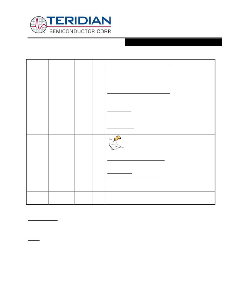
�FLSHCRL�
�0xB2�
�R/W�
�Bit 0 (� FLSH_PWE� ): Program Write Enable:�
�0� –� MOVX� commands� refer� to� XRAM� Space,� normal� operation�
�(default).�
�1� –� MOVX� @DPTR,A� moves� A� to� Program� Space� (Flash)� @�
�DPTR.�
�This� bit� is� automatically� reset� after� each� byte� written� to� flash.� Writes�
�to� this� bit� are� inhibited� when� interrupts� are� enabled.�
�W�
�R/W�
�R�
�Bit 1 (� FLSH_MEEN� ): Mass Erase Enable:�
�0� –� Mass� Erase� disabled� (default).�
�1� –� Mass� Erase� enabled.�
�Must� be� re-written� for� each� new� Mass� Erase� cycle.�
�Bit 6 (� SECURE� ):�
�Enables� security� provisions� that� prevent� external� reading� of� flash�
�memory� and� CE� program� RAM.� This� bit� is� reset� on� chip� reset� and�
�may� only� be� set.� Attempts� to� write� zero� are� ignored.�
�Bit 7 (� PREBOOT� ):�
�Indicates� that� the� preboot� sequence� is� active.�
�WDI�
�0xE8�
�R/W�
�R/W�
�W�
�Only� byte� operations� on� the� whole� WDI� register�
�should� be� used� when� writing� .� The� byte� must� have� all�
�bits� set� except� the� bits� that� are� to� be� cleared.�
�The� multi-purpose� register� WDI� contains� the� following� bits:�
�Bit 0 (� IE_XFER� ): XFER Interrupt Flag:�
�This� flag� monitors� the� XFER_BUSY� interrupt.� It� is� set� by� hardware�
�and� must� be� cleared� by� the� interrupt� handler�
�Bit 1: Reserved�
�Bit 7 (� WD_RST� ): WD Timer Reset:�
�Read:� Reads� the� PLL_FALL� interrupt� flag�
�Write� 0:� Clears� the� PLL_FALL� interrupt� flag�
�Write� 1:� Resets� the� watch� dog� timer�
�INTBITS�
�INT0…INT6�
�0xF8�
�R�
�Interrupt� inputs.� The� MPU� may� read� these� bits� to� see� the� input� to�
�external� interrupts� INT0,� INT1,� up� to� INT6.� These� bits� do� not� have�
�any� memory� and� are� primarily� intended� for� debug� use�
�Table� 11:� Special� Function� Registers�
�Instruction Set�
�All� instructions� of� the� generic� 8051� microcontroller� are� supported.� A� complete� list� of� the� instruction� set� and� of� the� associated�
�op-codes� is� contained� in� the� 71M6521� Software� User’s� Guide� (SUG).�
�UART�
�The� 71M6521BE� includes� a� UART� (UART0)� that� can� be� programmed� to� communicate� with� a� variety� of� AMR� modules.� A�
�second� UART� (UART1)� is� connected� to� the� optical� port,� as� described� in� the� optical� port� description.�
�The� UART� is� a� dedicated� 2-wire� serial� interface,� which� can� communicate� with� an� external� host� processor� at� up� to� 38,400� bits/s�
�((with� MPU� clock� =� 1.2288MHz).� The� operation� of� each� pin� is� as� follows:�
�RX� :� Serial� input� data� are� applied� at� this� pin.� Conforming� to� RS-232� standard,� the� bytes� are� input� LSB� first.�
�TX� :� This� pin� is� used� to� output� the� serial� data.� The� bytes� are� output� LSB� first.�
�Page:� 22� of� 97�
�?� 2005-2008� TERIDIAN� Semiconductor� Corporation�
�V1.0�
�相关PDF资料 |
PDF描述 |
|---|---|
| ABC44DRES | CONN EDGECARD 88POS .100 EYELET |
| RS3-4809SZ | CONV DC/DC 3W 20-60VIN 09VOUT |
| VI-BNK-EU-F1 | CONVERTER MOD DC/DC 40V 200W |
| 78M6610+PSU/B00 | IC ENERGY MEASURMENT 1PH 24TQFN |
| ACB65DHLT | CONN EDGECARD 130PS .050 DIP SLD |
相关代理商/技术参数 |
参数描述 |
|---|---|
| 71M6521BE-IGTR/F | 功能描述:计量片上系统 - SoC Residential Energy Meter IC RoHS:否 制造商:Maxim Integrated 核心:80515 MPU 处理器系列:71M6511 类型:Metering SoC 最大时钟频率:70 Hz 程序存储器大小:64 KB 数据 RAM 大小:7 KB 接口类型:UART 可编程输入/输出端数量:12 片上 ADC: 安装风格:SMD/SMT 封装 / 箱体:LQFP-64 封装:Reel |
| 71M6521BE-IGTR/F1 | 功能描述:计量片上系统 - SoC RoHS:否 制造商:Maxim Integrated 核心:80515 MPU 处理器系列:71M6511 类型:Metering SoC 最大时钟频率:70 Hz 程序存储器大小:64 KB 数据 RAM 大小:7 KB 接口类型:UART 可编程输入/输出端数量:12 片上 ADC: 安装风格:SMD/SMT 封装 / 箱体:LQFP-64 封装:Reel |
| 71M6521DE | 制造商:TERIDIAN 制造商全称:TERIDIAN 功能描述:Energy Meter IC |
| 71M6521DE-DB | 制造商:Maxim Integrated Products 功能描述:Development Boards & Kits - 8051 71M6521DE Demo Brd |
| 71M6521DE-IGT/F | 功能描述:计量片上系统 - SoC Residential Energy Meter IC RoHS:否 制造商:Maxim Integrated 核心:80515 MPU 处理器系列:71M6511 类型:Metering SoC 最大时钟频率:70 Hz 程序存储器大小:64 KB 数据 RAM 大小:7 KB 接口类型:UART 可编程输入/输出端数量:12 片上 ADC: 安装风格:SMD/SMT 封装 / 箱体:LQFP-64 封装:Reel |
发布紧急采购,3分钟左右您将得到回复。