- 您现在的位置:买卖IC网 > PDF目录20617 > 71M6521BE-IGT/F (Maxim Integrated)IC ENERGY METER 8K FLASH 64-LQFP PDF资料下载
参数资料
| 型号: | 71M6521BE-IGT/F |
| 厂商: | Maxim Integrated |
| 文件页数: | 45/97页 |
| 文件大小: | 0K |
| 描述: | IC ENERGY METER 8K FLASH 64-LQFP |
| 产品培训模块: | Lead (SnPb) Finish for COTS Obsolescence Mitigation Program |
| 标准包装: | 160 |
| 系列: | Single Converter Technology® |
| 测量误差: | 0.4% |
| 电源电压: | 3 V ~ 3.6 V |
| 测量仪表类型: | 单相,双相 |
| 工作温度: | -40°C ~ 85°C |
| 安装类型: | 表面贴装 |
| 封装/外壳: | 64-LQFP |
| 供应商设备封装: | 64-LQFP(10x10) |
| 包装: | 托盘 |
第1页第2页第3页第4页第5页第6页第7页第8页第9页第10页第11页第12页第13页第14页第15页第16页第17页第18页第19页第20页第21页第22页第23页第24页第25页第26页第27页第28页第29页第30页第31页第32页第33页第34页第35页第36页第37页第38页第39页第40页第41页第42页第43页第44页当前第45页第46页第47页第48页第49页第50页第51页第52页第53页第54页第55页第56页第57页第58页第59页第60页第61页第62页第63页第64页第65页第66页第67页第68页第69页第70页第71页第72页第73页第74页第75页第76页第77页第78页第79页第80页第81页第82页第83页第84页第85页第86页第87页第88页第89页第90页第91页第92页第93页第94页第95页第96页第97页
�� �
�
�71M6521BE�
�Energy� Meter� IC�
�DATA� SHEET�
�JANUARY� 2008�
�Hardware Watchdog Timer�
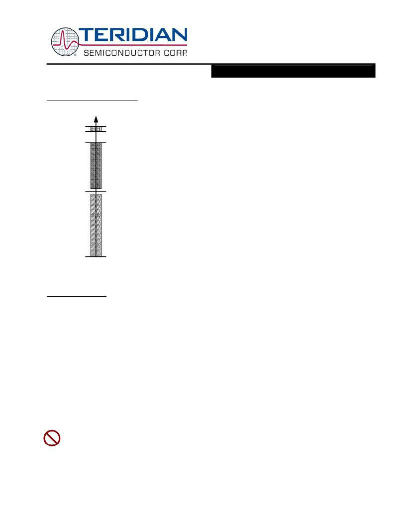
�V1�
�In� addition� to� the� basic� watchdog� timer� included� in� the� 80515� MPU,� an� independent,�
�robust,� fixed-duration,� watchdog� timer� (WDT)� is� included� in� the� device.� It� uses� the� crystal�
�V3P3�
�V3P3� -� 10mV�
�V3P3� -�
�400mV�
�WDT� dis-�
�abled�
�Normal�
�oscillator� as� its� time� base� and� must� be� refreshed� by� the� MPU� firmware� at� least� every� 1.5�
�seconds.� When� not� refreshed� on� time� the� WDT� overflows,� and� the� part� is� reset� as� if� the�
�RESET� pin� were� pulled� high,� except� that� the� I/O� RAM� bits� will� be� in� the� same� state� as� after�
�a� wake-up� from� SLEEP� or� LCD� modes� (see� the� I/O� RAM� description� for� a� list� of� I/O� RAM�
�bit� states� after� RESET� and� wake-up).� 4100� oscillator� cycles� (or� 125ms)� after� the� WDT�
�overflow,� the� MPU� will� be� launched� from� program� address� 0x0000.�
�VBIAS�
�0V�
�operation,�
�WDT�
�enabled�
�Battery�
�modes�
�A� status� bit,� WD_OVF� ,� is� set� when� WDT� overflow� occurs.� This� bit� is� powered� by� the�
�nonvolatile� supply� and� can� be� read� by� the� MPU� when� WAKE� rises� to� determine� if� the� part�
�is� initializing� after� a� WD� overflow� event� or� after� a� power-up.� After� it� is� read,� MPU� firmware�
�must� clear� WD_OVF� .� The� WD_OVF� bit� is� cleared� by� the� RESET� pin�
�There� is� no� internal� digital� state� that� deactivates� the� WDT.� For� debug� purposes,� however,�
�the� WDT� can� be� disabled� by� tying� the� V1� pin� to� V3P3� (see� Figure� 35).� Of� course,� this� also�
�deactivates� V1� power� fault� detection.� Since� there� is� no� firmware� way� to� disable� the� crystal�
�oscillator� or� the� WDT,� it� is� guaranteed� that� whatever� state� the� part� might� find� itself� in,� upon�
�watchdog� overflow,� the� part� will� be� reset� to� a� known� state.�
�Asserting� ICE_E� will� also� deactivate� the� WDT.� This� is� the� only� method� that� will� work� in�
�BROWNOUT� mode.�
�In� normal� operation,� the� WDT� is� reset� by� periodically� writing� a� one� to� the� WDT_RST� bit.� The�
�watchdog� timer� is� also� reset� when� the� internal� signal� WAKE=0� (see� section� on� Wake� Up�
�Behavior).�
�Figure� 14:� Functions� defined� by� V1.�
�Program Security�
�When� enabled,� the� security� feature� limits� the� ICE� to� global� flash� erase� operations� only.� All� other� ICE� operations� are� blocked.�
�This� guarantees� the� security� of� the� user’s� MPU� and� CE� program� code.� Security� is� enabled� by� MPU� code� that� is� executed� in� a�
�32� cycle� preboot� interval� before� the� primary� boot� sequence� begins.� Once� security� is� enabled,� the� only� way� to� disable� it� is� to�
�perform� a� global� erase� of� the� flash,� followed� by� a� chip� reset.�
�The� first� 32� cycles� of� the� MPU� boot� code� are� called� the� preboot� phase� because� during� this� phase� the� ICE� is� inhibited.� A� read-�
�only� status� bit,� PREBOOT� ,� identifies� these� cycles� to� the� MPU.� Upon� completion� of� preboot,� the� ICE� can� be� enabled� and� is�
�permitted� to� take� control� of� the� MPU.�
�SECURE� ,� the� security� enable� bit,� is� reset� whenever� the� chip� is� reset.� Hardware� associated� with� the� bit� permits� only� ones� to� be�
�written� to� it.� Thus,� preboot� code� may� set� SECURE� to� enable� the� security� feature� but� may� not� reset� it.� Once� SECURE� is� set,� the�
�preboot� code� is� protected� and� no� external� read� of� program� code� is� possible�
�Specifically,� when� SECURE� is� set:�
�?�
�?�
�?�
�The� ICE� is� limited� to� bulk� flash� erase� only.�
�Page� zero� of� flash� memory,� the� preferred� location� for� the� user’s� preboot� code,� may� not� be� page-erased� by� either�
�MPU� or� ICE.� Page� zero� may� only� be� erased� with� global� flash� erase.�
�Writes� to� page� zero,� whether� by� MPU� or� ICE� are� inhibited.�
�The� SECURE� bit� is� to� be� used� with� caution!� Inadvertently� setting� this� bit� will� inhibit� access� to� the� part� via� the� ICE�
�interface,� if� no� mechanism� for� actively� resetting� the� part� between� reset� and� erase� operations� is� provided� (see� ICE�
�Interface� description).�
�V1.0�
�?� 2005-2008� TERIDIAN� Semiconductor� Corporation�
�Page:� 45� of� 97�
�相关PDF资料 |
PDF描述 |
|---|---|
| ABC44DRES | CONN EDGECARD 88POS .100 EYELET |
| RS3-4809SZ | CONV DC/DC 3W 20-60VIN 09VOUT |
| VI-BNK-EU-F1 | CONVERTER MOD DC/DC 40V 200W |
| 78M6610+PSU/B00 | IC ENERGY MEASURMENT 1PH 24TQFN |
| ACB65DHLT | CONN EDGECARD 130PS .050 DIP SLD |
相关代理商/技术参数 |
参数描述 |
|---|---|
| 71M6521BE-IGTR/F | 功能描述:计量片上系统 - SoC Residential Energy Meter IC RoHS:否 制造商:Maxim Integrated 核心:80515 MPU 处理器系列:71M6511 类型:Metering SoC 最大时钟频率:70 Hz 程序存储器大小:64 KB 数据 RAM 大小:7 KB 接口类型:UART 可编程输入/输出端数量:12 片上 ADC: 安装风格:SMD/SMT 封装 / 箱体:LQFP-64 封装:Reel |
| 71M6521BE-IGTR/F1 | 功能描述:计量片上系统 - SoC RoHS:否 制造商:Maxim Integrated 核心:80515 MPU 处理器系列:71M6511 类型:Metering SoC 最大时钟频率:70 Hz 程序存储器大小:64 KB 数据 RAM 大小:7 KB 接口类型:UART 可编程输入/输出端数量:12 片上 ADC: 安装风格:SMD/SMT 封装 / 箱体:LQFP-64 封装:Reel |
| 71M6521DE | 制造商:TERIDIAN 制造商全称:TERIDIAN 功能描述:Energy Meter IC |
| 71M6521DE-DB | 制造商:Maxim Integrated Products 功能描述:Development Boards & Kits - 8051 71M6521DE Demo Brd |
| 71M6521DE-IGT/F | 功能描述:计量片上系统 - SoC Residential Energy Meter IC RoHS:否 制造商:Maxim Integrated 核心:80515 MPU 处理器系列:71M6511 类型:Metering SoC 最大时钟频率:70 Hz 程序存储器大小:64 KB 数据 RAM 大小:7 KB 接口类型:UART 可编程输入/输出端数量:12 片上 ADC: 安装风格:SMD/SMT 封装 / 箱体:LQFP-64 封装:Reel |
发布紧急采购,3分钟左右您将得到回复。