- 您现在的位置:买卖IC网 > PDF目录298521 > 72V293L6PFG (INTEGRATED DEVICE TECHNOLOGY INC) 64K X 18 OTHER FIFO, 4 ns, PQFP80 PDF资料下载
参数资料
| 型号: | 72V293L6PFG |
| 厂商: | INTEGRATED DEVICE TECHNOLOGY INC |
| 元件分类: | FIFO |
| 英文描述: | 64K X 18 OTHER FIFO, 4 ns, PQFP80 |
| 封装: | GREEN, PLASTIC, TQFP-80 |
| 文件页数: | 5/45页 |
| 文件大小: | 381K |
| 代理商: | 72V293L6PFG |
第1页第2页第3页第4页当前第5页第6页第7页第8页第9页第10页第11页第12页第13页第14页第15页第16页第17页第18页第19页第20页第21页第22页第23页第24页第25页第26页第27页第28页第29页第30页第31页第32页第33页第34页第35页第36页第37页第38页第39页第40页第41页第42页第43页第44页第45页
13
IDT72V263/273/283/293/103/113 3.3V HIGH DENSITY SUPERSYNC IITM NARROW BUS FIFO
8K x 18, 16K x 9/18, 32K x 9/18, 64K x 9/18, 128K x 9/18, 256K x 9/18, 512K x9
COMMERCIAL AND INDUSTRIAL
TEMPERATURE RANGES
IDT72V223/233/243/253/263/273/283/293 3.3V HIGH DENSITY SUPERSYNC IITM NARROW BUS FIFO
512 x 18, 1K x 9/18, 2K x 9/18, 4K x 9/18, 8K x 9/18, 16K x 9/18, 32K x 9/18, 64K x 9/18, 128K x 9
FEBRUARY 11, 2009
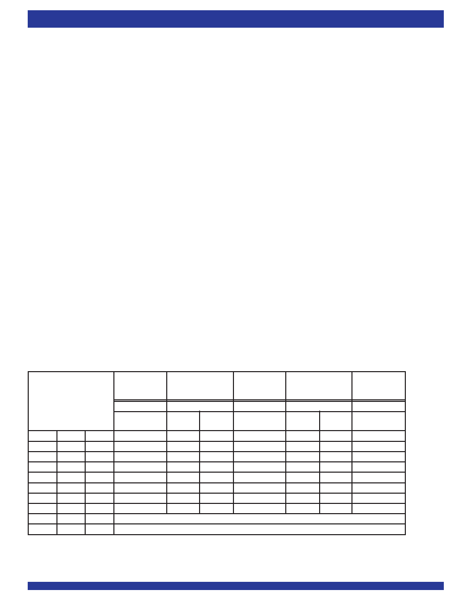
TABLE 2 DEFAULT PROGRAMMABLE FLAG OFFSETS
IDT72V253
IDT72V223
IDT72V263
IDT72V233
IDT72V243
IDT72V273
IDT72V283
IDT72V293
Offsets n,m
All Other
x9 to x9
All Other
x9 to x9
LD
FSEL0
FSEL1
All Modes
Modes
Mode
All Modes
Modes
Mode
All Modes
L
H
511
16,383
L
H
L
255
8,191
L
H
63
4,095
H
L
H
15
31
2,047
H
L
31
1,023
H
L
7
15
511
H
3
7
255
L
127
H
X
Serial Programming Mode(3)
L
X
Parallel Programming Mode(4)
(32,769-m) writes for the IDT72V273, (65,537-m) writes for the IDT72V283
and (131,073-m) writes for the IDT72V293. The offset m is the full offset value.
The default setting for these values are stated in the footnote of Table 2.
WhentheFIFOisfull,theInputReady(
IR)flagwillgoHIGH,inhibitingfurther
write operations. If no reads are performed after a reset,
IR will go HIGH after
D writes to the FIFO. If x18 Input or x18 Output bus Width is selected, D = 513
writes for the IDT72V223, 1,025 writes for the IDT72V233, 2,049 writes for the
IDT72V243, 4,097 writes for the IDT72V253, 8,193 writes for the IDT72V263,
16,385 writes for the IDT72V273, 32,769 writes for the IDT72V283 and 65,537
writesfortheIDT72V293.Ifbothx9Inputandx9OutputbusWidthsareselected,
D = 1,025 writes for the IDT72V223, 2,049 writes for the IDT72V233, 4,097
writes for the IDT72V243, 8,193 writes for the IDT72V253, 16,385 writes for
the IDT72V263, 32,769 writes for the IDT72V273, 65,537 writes for the
IDT72V283 and 131,073 writes for the IDT72V293, respectively. Note that the
additionalwordinFWFTmodeisduetothecapacityofthememoryplusoutput
register.
If the FIFO is full, the first read operation will cause the
IR flag to go LOW.
Subsequent read operations will cause the
PAF and HF to go HIGH at the
conditions described in Table 4. If further read operations occur, without write
operations, the
PAEwillgoLOWwhentherearen+1wordsintheFIFO,where
n is the empty offset value. Continuing read operations will cause the FIFO to
become empty. When the last word has been read from the FIFO,
OR will go
HIGHinhibitingfurtherreadoperations.
RENisignoredwhentheFIFOisempty.
When configured in FWFT mode, the
OR flag output is triple register-
buffered, and the
IR flag output is double register-buffered.
Relevant timing diagrams for FWFT mode can be found in Figure 9, 10 and
12.
PROGRAMMING FLAG OFFSETS
FullandEmptyFlagoffsetvaluesareuserprogrammable.TheIDT72V223/
72V233/72V243/72V253/72V263/72V273/72V283/72V293 has internalreg-
isters for these offsets. There are eight default offset values selectable during
MasterReset.TheseoffsetvaluesareshowninTable2.Offsetvaluescanalso
be programmed into the FIFO in one of two ways; serial or parallel loading
method. The selection of the loading method is done using the
LD (Load)pin.
During Master Reset, the state of the
LD input determines whether serial or
parallelflagoffsetprogrammingisenabled.AHIGHon
LDduringMasterReset
selectsserialloadingofoffsetvalues.ALOWon
LDduringMasterResetselects
parallel loading of offset values.
In addition to loading offset values into the FIFO, it is also possible to read
the current offset values. Offset values can be read via the parallel output port
Q0-Qn, regardless of the programming mode selected (serial or parallel). It is
not possible to read the offset values in serial fashion.
Figure 3, Programmable Flag Offset Programming Sequence, summaries
thecontrolpinsandsequenceforbothserialandparallelprogrammingmodes.
For a more detailed description, see discussion that follows.
Theoffsetregistersmaybeprogrammed(andreprogrammed)anytimeafter
Master Reset, regardless of whether serial or parallel programming has been
selected. Valid programming ranges are from 0 to D-1.
SYNCHRONOUS vs ASYNCHRONOUS PROGRAMMABLE FLAG
TIMING SELECTION
The IDT72V223/72V233/72V243/72V253/72V263/72V273/72V283/
72V293 can be configured during the Master Reset cycle with either synchro-
nous or asynchronous timing for
PAF and PAE flags by use of the PFM pin.
If synchronous
PAF/PAE configuration is selected (PFM, HIGH during
MRS), the PAF is asserted and updated on the rising edge of WCLK only and
not RCLK. Similarly,
PAEisassertedandupdatedontherisingedgeofRCLK
only and not WCLK. For detail timing diagrams, see Figure 18 for synchronous
PAF timing and Figure 19 for synchronous PAE timing.
If asynchronous
PAF/PAE configuration is selected (PFM, LOW during
MRS),thePAFisassertedLOWontheLOW-to-HIGHtransitionofWCLKand
PAFisresettoHIGHontheLOW-to-HIGHtransitionofRCLK.Similarly,PAE
isassertedLOWontheLOW-to-HIGHtransitionofRCLK.
PAEisresettoHIGH
ontheLOW-to-HIGHtransitionofWCLK.Fordetailtimingdiagrams,seeFigure
20 for asynchronous
PAFtimingandFigure21forasynchronousPAEtiming.
NOTES:
1. n = empty offset for
PAE.
2. m = full offset for
PAF.
3. As well as selecting serial programming mode, one of the default values will also be loaded depending on the state of FSEL0 & FSEL1.
4. As well as selecting parallel programming mode, one of the default values will also be loaded depending on the state of FSEL0 & FSEL1.
相关PDF资料 |
PDF描述 |
|---|---|
| 72V233L6BCG | 1K X 18 OTHER FIFO, 4 ns, PBGA100 |
| 72V3613L20PQF | 64 X 36 OTHER FIFO, 12 ns, PQFP132 |
| 72V3660L6PFG8 | 4K X 36 OTHER FIFO, 4 ns, PQFP128 |
| 7305-0-15-01-47-01-10-0 | BERYLLIUM COPPER, TIN LEAD (300) OVER NICKEL FINISH, PCB TERMINAL |
| 7305-0-15-15-47-27-10-0 | BERYLLIUM COPPER, GOLD (30) OVER NICKEL FINISH, PCB TERMINAL |
相关代理商/技术参数 |
参数描述 |
|---|---|
| 72V293L7-5BC | 功能描述:先进先出 128Kx9/ 64Kx18 3.3V SUPER SYNC II 先进先出 RoHS:否 制造商:IDT 电路数量: 数据总线宽度:18 bit 总线定向:Unidirectional 存储容量:4 Mbit 定时类型:Synchronous 组织:256 K x 18 最大时钟频率:100 MHz 访问时间:10 ns 电源电压-最大:3.6 V 电源电压-最小:6 V 最大工作电流:35 mA 最大工作温度:+ 85 C 封装 / 箱体:TQFP-80 封装: |
| 72V293L7-5BCI | 功能描述:先进先出 128Kx9/ 64Kx18 3.3V SUPER SYNC II 先进先出 RoHS:否 制造商:IDT 电路数量: 数据总线宽度:18 bit 总线定向:Unidirectional 存储容量:4 Mbit 定时类型:Synchronous 组织:256 K x 18 最大时钟频率:100 MHz 访问时间:10 ns 电源电压-最大:3.6 V 电源电压-最小:6 V 最大工作电流:35 mA 最大工作温度:+ 85 C 封装 / 箱体:TQFP-80 封装: |
| 72V293L7-5PF | 功能描述:先进先出 128Kx9/ 64Kx18 3.3V SUPER SYNC II 先进先出 RoHS:否 制造商:IDT 电路数量: 数据总线宽度:18 bit 总线定向:Unidirectional 存储容量:4 Mbit 定时类型:Synchronous 组织:256 K x 18 最大时钟频率:100 MHz 访问时间:10 ns 电源电压-最大:3.6 V 电源电压-最小:6 V 最大工作电流:35 mA 最大工作温度:+ 85 C 封装 / 箱体:TQFP-80 封装: |
| 72V293L7-5PF8 | 功能描述:先进先出 128Kx9/ 64Kx18 3.3V SUPER SYNC II 先进先出 RoHS:否 制造商:IDT 电路数量: 数据总线宽度:18 bit 总线定向:Unidirectional 存储容量:4 Mbit 定时类型:Synchronous 组织:256 K x 18 最大时钟频率:100 MHz 访问时间:10 ns 电源电压-最大:3.6 V 电源电压-最小:6 V 最大工作电流:35 mA 最大工作温度:+ 85 C 封装 / 箱体:TQFP-80 封装: |
| 72V293L7-5PF9 | 制造商:Integrated Device Technology Inc 功能描述:FIFO Mem Sync Dual Depth/Width Uni-Dir 64K x 18/128K x 9 80-Pin TQFP |
发布紧急采购,3分钟左右您将得到回复。