参数资料
| 型号: | AD7194BCPZ |
| 厂商: | Analog Devices Inc |
| 文件页数: | 13/57页 |
| 文件大小: | 0K |
| 描述: | IC ADC 24BIT SPI 4.8K 32-LFCSP |
| 产品培训模块: | Weigh Scale Introduction |
| 标准包装: | 1 |
| 位数: | 24 |
| 采样率(每秒): | 4.8k |
| 数据接口: | DSP,MICROWIRE?,QSPI?,串行,SPI? |
| 转换器数目: | 1 |
| 电压电源: | 模拟和数字 |
| 工作温度: | -40°C ~ 105°C |
| 安装类型: | 表面贴装 |
| 封装/外壳: | 32-WFQFN 裸露焊盘,CSP |
| 供应商设备封装: | 32-LFCSP-WQ(5x5) |
| 包装: | 管件 |
| 输入数目和类型: | 8 个差分,单极;8 个差分,双极;16 个伪差分,单极;16 伪差分,双极 |
| 产品目录页面: | 777 (CN2011-ZH PDF) |
| 其它名称: | AD7194BRUZ AD7194BRUZ-ND |
第1页第2页第3页第4页第5页第6页第7页第8页第9页第10页第11页第12页当前第13页第14页第15页第16页第17页第18页第19页第20页第21页第22页第23页第24页第25页第26页第27页第28页第29页第30页第31页第32页第33页第34页第35页第36页第37页第38页第39页第40页第41页第42页第43页第44页第45页第46页第47页第48页第49页第50页第51页第52页第53页第54页第55页第56页第57页
Data Sheet
AD7194
Rev. A | Page 19 of 56
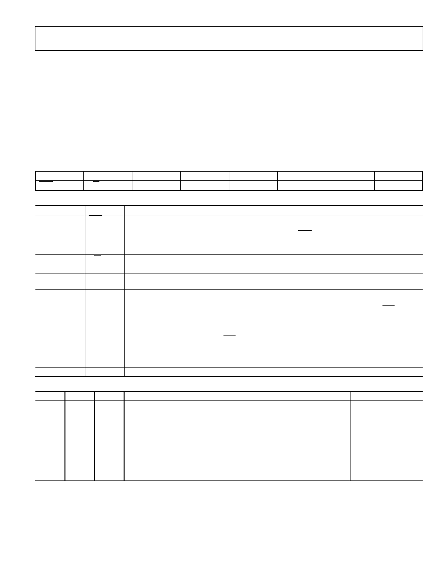
COMMUNICATIONS REGISTER
RS2, RS1, RS0 = 000
The communications register is an 8-bit write-only register. All
communications to the part must start with a write operation to
the communications register. The data written to the communi-
cations register determine whether the next operation is a read
or write operation and in which register this operation occurs. For
read or write operations, when the subsequent read or write oper-
ation to the selected register is complete, the interface returns to
where it expects a write operation to the communications register.
This is the default state of the interface and, on power-up or after
a reset, the ADC is in this default state waiting for a write
operation to the communications register. In situations where the
interface sequence is lost, a write operation of at least 40 serial
clock cycles with DIN high returns the ADC to this default state
by resetting the entire part. Table 16 outlines the bit designations
for the communications register. CR0 through CR7 indicate the
bit location, CR denoting that the bits are in the communications
register. CR7 denotes the first bit of the data stream. The number
in parentheses indicates the power-on/reset default status of
that bit.
CR7
CR6
CR5
CR4
CR3
CR2
CR1
CR0
WEN(0)
R/W(0)
RS2(0)
RS1(0)
RS0(0)
CREAD(0)
0(0)
Table 16. Communications Register (CR) Bit Designations
Bit Location
Bit Name
Description
CR7
WEN
Write enable bit. For a write to the communications register to occur, 0 must be written to this bit. If a 1 is
the first bit written, the part does not clock onto subsequent bits in the register; rather, it stays at this bit
location until a 0 is written to this bit. After a 0 is written to the WEN bit, the next seven bits are loaded to
the communications register. Idling the DIN pin high between data transfers minimizes the effects of
spurious SCLK pulses on the serial interface.
CR6
R/W
0 in this bit location indicates that the next operation is a write to a specified register.
1 in this bit position indicates that the next operation is a read from the designated register.
CR5 to CR3
RS2 to RS0
Register address bits. These address bits are used to select which registers of the ADC are selected during
the serial interface communication (see Table 17).
CR2
CREAD
Continuous read of the data register. When this bit is set to 1 (and the data register is selected), the serial
interface is configured so that the data register can be continuously read; that is, the contents of the data
register are automatically placed on the DOUT pin when the SCLK pulses are applied after the RDY pin
goes low to indicate that a conversion is complete. The communications register does not have to be
written to for subsequent data reads. To enable continuous read, Instruction 01011100 must be written to
the communications register. To disable continuous read, Instruction 01011000 must be written to the
communications register while the RDY pin is low. While continuous read is enabled, the ADC monitors
activity on the DIN line so that it can receive the instruction to disable continuous read. Additionally, a
reset occurs if 40 consecutive 1s occur on DIN; therefore, hold DIN low until an instruction is written to
the device.
CR1 to CR0
0
These bits must be programmed to Logic 0 for correct operation.
Table 17. Register Selection
RS2
RS1
RS0
Register
Register Size
0
Communications register during a write operation
8 bits
0
Status register during a read operation
8 bits
0
1
Mode register
24 bits
0
1
0
Configuration register
24 bits
0
1
Data register/data register plus status information
24 bits/32 bits
1
0
ID register
8 bits
1
0
1
GPOCON register
8 bits
1
0
Offset register
24 bits
1
Full-scale register
24 bits
相关PDF资料 |
PDF描述 |
|---|---|
| AD7195BCPZ-RL7 | IC AFE 24BIT 4.8K 32LFSP |
| AD7225BQ | IC DAC 8BIT QUAD W/AMP 24-CDIP |
| AD7226BQ | IC DAC 8BIT QUAD W/AMP 20-CDIP |
| AD7228CQ | IC DAC 8BIT OCTAL W/AMP 24-CDIP |
| AD7233BNZ | IC DAC 12BIT SRL W/AMP 8PDIP |
相关代理商/技术参数 |
参数描述 |
|---|---|
| AD7194BCPZ-REEL | 功能描述:IC ADC 24BIT SPI 4.8KHZ 32LFCSP RoHS:是 类别:集成电路 (IC) >> 数据采集 - 模数转换器 系列:- 标准包装:1,000 系列:- 位数:16 采样率(每秒):45k 数据接口:串行 转换器数目:2 功率耗散(最大):315mW 电压电源:模拟和数字 工作温度:0°C ~ 70°C 安装类型:表面贴装 封装/外壳:28-SOIC(0.295",7.50mm 宽) 供应商设备封装:28-SOIC W 包装:带卷 (TR) 输入数目和类型:2 个单端,单极 |
| AD7194BCPZ-REEL7 | 功能描述:IC ADC 24BIT SPI 4.8KHZ 32LFCSP RoHS:是 类别:集成电路 (IC) >> 数据采集 - 模数转换器 系列:- 标准包装:1,000 系列:- 位数:16 采样率(每秒):45k 数据接口:串行 转换器数目:2 功率耗散(最大):315mW 电压电源:模拟和数字 工作温度:0°C ~ 70°C 安装类型:表面贴装 封装/外壳:28-SOIC(0.295",7.50mm 宽) 供应商设备封装:28-SOIC W 包装:带卷 (TR) 输入数目和类型:2 个单端,单极 |
| AD7195 | 制造商:AD 制造商全称:Analog Devices 功能描述:4.8 kHz, Ultralow Noise, 24-Bit Sigma-Delta ADC with PGA and AC Excitation |
| AD7195BCPZ | 功能描述:IC AFE 24BIT 4.8K 32LFSP RoHS:是 类别:集成电路 (IC) >> 数据采集 - 模拟前端 (AFE) 系列:- 产品培训模块:Lead (SnPb) Finish for COTS Obsolescence Mitigation Program 标准包装:2,500 系列:- 位数:- 通道数:2 功率(瓦特):- 电压 - 电源,模拟:3 V ~ 3.6 V 电压 - 电源,数字:3 V ~ 3.6 V 封装/外壳:32-VFQFN 裸露焊盘 供应商设备封装:32-QFN(5x5) 包装:带卷 (TR) |
| AD7195BCPZ | 制造商:Analog Devices 功能描述:IC ADC 24BIT 4.8KSPS CSP-32 |
发布紧急采购,3分钟左右您将得到回复。