参数资料
| 型号: | AD7194BCPZ |
| 厂商: | Analog Devices Inc |
| 文件页数: | 19/57页 |
| 文件大小: | 0K |
| 描述: | IC ADC 24BIT SPI 4.8K 32-LFCSP |
| 产品培训模块: | Weigh Scale Introduction |
| 标准包装: | 1 |
| 位数: | 24 |
| 采样率(每秒): | 4.8k |
| 数据接口: | DSP,MICROWIRE?,QSPI?,串行,SPI? |
| 转换器数目: | 1 |
| 电压电源: | 模拟和数字 |
| 工作温度: | -40°C ~ 105°C |
| 安装类型: | 表面贴装 |
| 封装/外壳: | 32-WFQFN 裸露焊盘,CSP |
| 供应商设备封装: | 32-LFCSP-WQ(5x5) |
| 包装: | 管件 |
| 输入数目和类型: | 8 个差分,单极;8 个差分,双极;16 个伪差分,单极;16 伪差分,双极 |
| 产品目录页面: | 777 (CN2011-ZH PDF) |
| 其它名称: | AD7194BRUZ AD7194BRUZ-ND |
第1页第2页第3页第4页第5页第6页第7页第8页第9页第10页第11页第12页第13页第14页第15页第16页第17页第18页当前第19页第20页第21页第22页第23页第24页第25页第26页第27页第28页第29页第30页第31页第32页第33页第34页第35页第36页第37页第38页第39页第40页第41页第42页第43页第44页第45页第46页第47页第48页第49页第50页第51页第52页第53页第54页第55页第56页第57页
Data Sheet
AD7194
Rev. A | Page 25 of 56
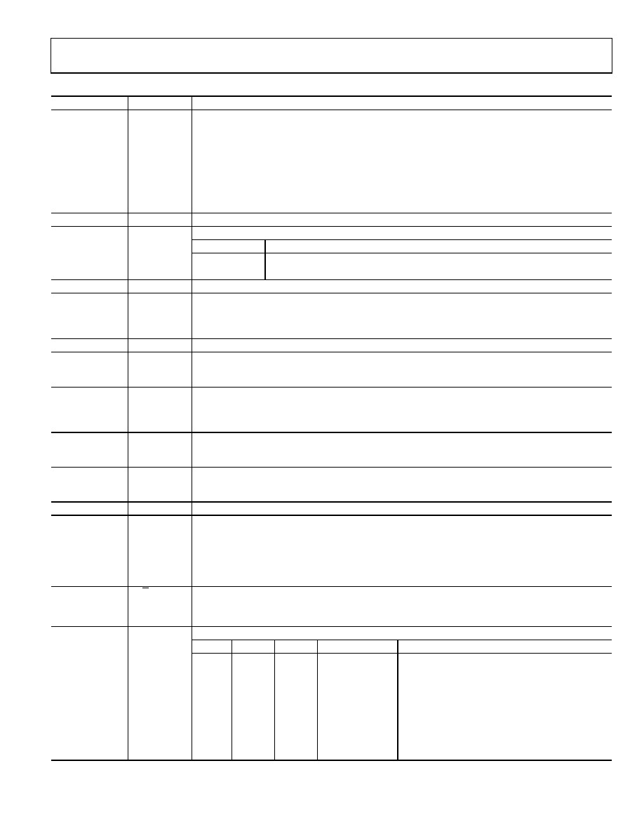
Table 21. Configuration Register Bit Designations
Bit Location
Bit Name
Description
CON23
Chop
Chop enable bit.
When the chop bit is cleared, chop is disabled. With chop disabled, higher conversion rates are allowed.
For an FS word of 96 decimal and the sinc4 filter selected, the conversion time is 20 ms and the settling
time is 80 ms. However, at low gains, periodic calibrations may be required to remove the offset and
offset drift.
When the chop bit is set, chop is enabled. When chop is enabled, the offset and offset drift of the ADC
are continuously removed. However, this increases the conversion time and settling time of the ADC.
For example, when FS = 96 decimal and the sinc4 filter is selected, the conversion time with chop
enabled equals 80 ms and the settling time equals 160 ms.
CON22, CON21
0
These bits must be programmed with a Logic 0 for correct operation.
CON20
REFSEL
Reference select bits. The reference source for the ADC is selected using these bits.
REFSEL
Reference Voltage
0
External reference applied between REFIN1(+) and REFIN1().
1
External reference applied between the AIN3/P1/REFIN2(+) and AIN4/P0/REFIN2() pins.
CON19
0
This bit must be programmed with a Logic 0 for correct operation.
CON18
Pseudo
Pseudo differential analog inputs. When the pseudo bit is set to 1, the AD7194 is configured to have 16
pseudo differential analog inputs with AINCOM as the common negative terminal. Bits CH7 to CH4
select the positive input terminal while bits CH3 to CH0 have no effect. When the pseudo bit is set to 0,
channel selection is controlled using the CH7 to CH0 bits.
CON17
0
This bit must be programmed with a Logic 0 for correct operation.
CON16
Temp
Temperature sensor select bit. When the Temp bit is set to 1, the internal temperature sensor is selected. When
the Temp bit is low, the analog input channel as determined by the Pseudo bit and the CH7 to CH0 bits is
selected. The temperature sensor does not have a unique code in bits CHD3 to CHD0 of the status register.
CON16 to CON8
CH7 to CH0
Channel select bits. These bits select which channel is enabled on the AD7194 (see Table 22 to Table 24).
The conversion on each channel requires the complete settling time. The four LSBs of the status register
indicate the channel corresponding to the conversion in the data register. The four LSBs correspond to
bits CH7 to CH3, that is, the positive analog input terminal.
CON7
Burn
When this bit is set to 1, the 500 nA current sources in the signal path are enabled. When Burn = 0, the
burnout currents are disabled. The burnout currents can be enabled only when the buffer is active and
when chop is disabled.
CON6
REFDET
Enables the reference detect function. When set, the NOREF bit in the status register indicates when the
external reference being used by the ADC is open circuit or less than 0.6 V maximum. The reference
detect circuitry operates only when the ADC is active.
CON5
0
This bit must be programmed with a Logic 0 for correct operation.
CON4
BUF
Enables the buffer on the analog inputs.
If BUF is set, the analog inputs are buffered, allowing the user to place source impedances on the front
end without contributing gain errors to the system. When the buffer is enabled, it requires some head-
room; therefore, the voltage on any input pin must be limited to 250 mV within the power supply rails.
If cleared, the analog inputs are unbuffered, lowering the power consumption of the device. With the
buffer disabled, the voltage on the analog input pins can be from 50 mV below AGND to 50 mV above AVDD.
CON3
U/B
Polarity select bit.
When this bit is set, unipolar operation is selected.
When this bit is cleared, bipolar operation is selected.
CON2 to CON0
G2 to G0
Gain select bits. These bits are written by the user to select the ADC input range as follows:
G2
G1
G0
Gain
ADC Input Range (2.5 V Reference)
0
1
±2.5 V
0
1
Reserved
0
1
0
Reserved
0
1
8
±312.5 mV
1
0
16
±156.2 mV
1
0
1
32
±78.125 mV
1
0
64
±39.06 mV
1
128
±19.53 mV
相关PDF资料 |
PDF描述 |
|---|---|
| AD7195BCPZ-RL7 | IC AFE 24BIT 4.8K 32LFSP |
| AD7225BQ | IC DAC 8BIT QUAD W/AMP 24-CDIP |
| AD7226BQ | IC DAC 8BIT QUAD W/AMP 20-CDIP |
| AD7228CQ | IC DAC 8BIT OCTAL W/AMP 24-CDIP |
| AD7233BNZ | IC DAC 12BIT SRL W/AMP 8PDIP |
相关代理商/技术参数 |
参数描述 |
|---|---|
| AD7194BCPZ-REEL | 功能描述:IC ADC 24BIT SPI 4.8KHZ 32LFCSP RoHS:是 类别:集成电路 (IC) >> 数据采集 - 模数转换器 系列:- 标准包装:1,000 系列:- 位数:16 采样率(每秒):45k 数据接口:串行 转换器数目:2 功率耗散(最大):315mW 电压电源:模拟和数字 工作温度:0°C ~ 70°C 安装类型:表面贴装 封装/外壳:28-SOIC(0.295",7.50mm 宽) 供应商设备封装:28-SOIC W 包装:带卷 (TR) 输入数目和类型:2 个单端,单极 |
| AD7194BCPZ-REEL7 | 功能描述:IC ADC 24BIT SPI 4.8KHZ 32LFCSP RoHS:是 类别:集成电路 (IC) >> 数据采集 - 模数转换器 系列:- 标准包装:1,000 系列:- 位数:16 采样率(每秒):45k 数据接口:串行 转换器数目:2 功率耗散(最大):315mW 电压电源:模拟和数字 工作温度:0°C ~ 70°C 安装类型:表面贴装 封装/外壳:28-SOIC(0.295",7.50mm 宽) 供应商设备封装:28-SOIC W 包装:带卷 (TR) 输入数目和类型:2 个单端,单极 |
| AD7195 | 制造商:AD 制造商全称:Analog Devices 功能描述:4.8 kHz, Ultralow Noise, 24-Bit Sigma-Delta ADC with PGA and AC Excitation |
| AD7195BCPZ | 功能描述:IC AFE 24BIT 4.8K 32LFSP RoHS:是 类别:集成电路 (IC) >> 数据采集 - 模拟前端 (AFE) 系列:- 产品培训模块:Lead (SnPb) Finish for COTS Obsolescence Mitigation Program 标准包装:2,500 系列:- 位数:- 通道数:2 功率(瓦特):- 电压 - 电源,模拟:3 V ~ 3.6 V 电压 - 电源,数字:3 V ~ 3.6 V 封装/外壳:32-VFQFN 裸露焊盘 供应商设备封装:32-QFN(5x5) 包装:带卷 (TR) |
| AD7195BCPZ | 制造商:Analog Devices 功能描述:IC ADC 24BIT 4.8KSPS CSP-32 |
发布紧急采购,3分钟左右您将得到回复。