- 您现在的位置:买卖IC网 > PDF目录10118 > AD7713ARZ-REEL (Analog Devices Inc)IC ADC 24BIT SIGMA-DELTA 24SOIC PDF资料下载
参数资料
| 型号: | AD7713ARZ-REEL |
| 厂商: | Analog Devices Inc |
| 文件页数: | 7/28页 |
| 文件大小: | 0K |
| 描述: | IC ADC 24BIT SIGMA-DELTA 24SOIC |
| 标准包装: | 1,000 |
| 位数: | 24 |
| 采样率(每秒): | 205 |
| 数据接口: | 串行 |
| 转换器数目: | 1 |
| 功率耗散(最大): | 5.5mW |
| 电压电源: | 模拟和数字 |
| 工作温度: | -40°C ~ 85°C |
| 安装类型: | 表面贴装 |
| 封装/外壳: | 24-SOIC(0.295",7.50mm 宽) |
| 供应商设备封装: | 24-SOIC W |
| 包装: | 带卷 (TR) |
| 输入数目和类型: | 1 个单端,单极;1 个差分,单极;1 个差分,双极 |
第1页第2页第3页第4页第5页第6页当前第7页第8页第9页第10页第11页第12页第13页第14页第15页第16页第17页第18页第19页第20页第21页第22页第23页第24页第25页第26页第27页第28页
REV. D
AD7713
–15–
In any case, the error introduced due to longer charging times is
a gain error that can be removed using the system calibration
capabilities of the AD7713 provided that the resultant span is
within the span limits of the system calibration techniques for
the AD7713.
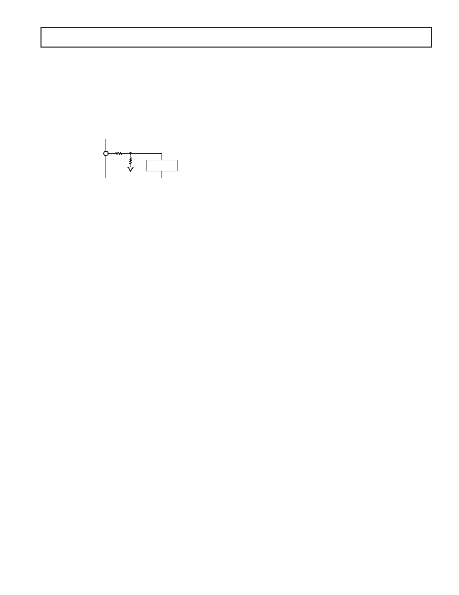
The AIN3 input contains a resistive attenuation network as
outlined in Figure 8. The typical input impedance on this input
is 44 k
. As a result, the AIN3 input should be driven from a
low impedance source.
AIN3
33k
11k
VBIAS
MODULATOR
CIRCUIT
Figure 8. AIN3 Input Impedance
ANALOG INPUT FUNCTIONS
Analog Input Ranges
The analog inputs on the AD7713 provide the user with consid-
erable flexibility in terms of analog input voltage ranges. Two of
the inputs are differential, programmable-gain, input channels
that can handle either unipolar or bipolar input signals. The
common-mode range of these inputs is from AGND to AVDD,
provided that the absolute value of the analog input voltage lies
between AGND – 30 mV and AVDD + 30 mV. The third analog
input is a single-ended, programmable gain high-level input that
accepts analog input ranges of 0 to 4
VREF/GAIN.
The dc input leakage current on the AIN1 and AIN2 inputs
is 10 pA maximum at 25
°C (±1 nA over temperature). This
results in a dc offset voltage developed across the source
impedance. However, this dc offset effect can be compensated
for by a combination of the differential input capability of the
part and its system calibration mode. The dc input current on
the AIN3 input depends on the input voltage. For the nominal
input voltage range of 10 V, the input current is 225
A typ.
Burn Out Current
The AIN1(+) input of the AD7713 contains a 1
A current source
that can be turned on/off via the control register. This current
source can be used in checking that a transducer has not burnt out
or gone open circuit before attempting to take measurements on
that channel. If the current is turned on and is allowed flow into
the transducer and a measurement of the input voltage on the
AIN1 input is taken, it can indicate that the transducer is not func-
tioning correctly. For normal operation, this burn out current is
turned off by writing a 0 to the BO bit in the control register.
RTD Excitation Currents
The AD7713 also contains two matched 200
A constant cur-
rent sources which are provided at the RTD1 and RTD2 pins of
the device. These currents can be turned on/off via the control
register. Writing a 1 to the RO bit of the control register enables
these excitation currents.
For 4-wire RTD applications, one of these excitation currents is
used to provide the excitation current for the RTD; the second
current source can be left unconnected. For 3-wire RTD con-
figurations, the second on-chip current source can be used
to eliminate errors due to voltage drops across lead resistances.
Figures 19 and 20 in the Application section show some RTD
configurations with the AD7713.
The temperature coefficient of the RTD current sources is
typically 20 ppm/
°C with a typical matching between the
temperature coefficients of both current sources of 3 ppm/
°C.
For applications where the absolute value of the temperature
coefficient is too large, the following schemes can be used to
remove the drift error.
The conversion result from the AD7713 is ratiometric to the
VREF voltage. Therefore, if the VREF voltage varies with the RTD
temperature coefficient, the temperature drift from the current
source will be removed. For 4-wire RTD applications, the refer-
ence voltage can be made ratiometric to the RTD current source
by using the second current with a low TC resistor to generate the
reference voltage for the part. In this case, if a 12.5 k
resistor is
used, the 200
A current source generates 2.5 V across the resistor.
This 2.5 V can be applied to the REF IN(+) input of the AD7713
and the REF IN(–) input at ground will supply a VREF of 2.5 V for
the part. For 3-wire RTD configurations, the reference voltage for
the part is generated by placing a low TC resistor (12.5 k
for
2.5 V reference) in series with one of the constant current sources.
The RTD current sources can be driven to within 2 V of AVDD.
The reference input of the AD7713 is differential so the REF IN(+)
and REF IN(–) of the AD7713 are driven from either side of the
resistor. Both schemes ensure that the reference voltage for the part
tracks the RTD current sources over temperature and, thereby,
removes the temperature drift error.
Bipolar/Unipolar Inputs
Two analog inputs on the AD7713 can accept either unipolar or
bipolar input voltage ranges while the third channel accepts only
unipolar signals. Bipolar or unipolar options for AIN1 and AIN2
are chosen by programming the B/U bit of the control register.
This programs both channels for either unipolar or bipolar opera-
tion. Programming the part for either unipolar or bipolar operation
does not change any of the input signal conditioning; it simply
changes the data output coding. The data coding is binary for
unipolar inputs and offset binary for bipolar inputs.
The AIN1 and AIN2 input channels are differential, and as a
result, the voltage to which the unipolar and bipolar signals are
referenced is the voltage on the AIN1(–) and AIN2(–) inputs. For
example, if AIN1(–) is 1.25 V and the AD7713 is configured for
unipolar operation with a gain of 1 and a VREF of 2.5 V, the input
voltage range on the AIN1(+) input is 1.25 V to 3.75 V. For the
AIN3 input, the input signals are referenced to AGND.
REFERENCE INPUT
The reference inputs of the AD7713, REF IN(+) and REF IN(–),
provide a differential reference input capability. The common-
mode range for these differential inputs is from VSS to AVDD. The
nominal differential voltage, VREF (REF IN(+) – REF IN(–)), is
2.5 V for specified operation, but the reference voltage can go to
5 V with no degradation in performance, provided that the
absolute value of REF IN(+) and REF IN(–) does not exceed
its AVDD and AGND limits. The part is also functional with
VREF voltages down to 1 V, but with degraded performance as the
output noise will, in terms of LSB size, be larger. REF IN(+)
must always be greater than REF IN(–) for correct operation of
the AD7713.
Both reference inputs provide a high impedance, dynamic load
similar to the analog inputs. The maximum dc input leakage cur-
rent is 10 pA (
±1 nA over temperature), and source resistance
may result in gain errors on the part. The reference inputs
相关PDF资料 |
PDF描述 |
|---|---|
| MS27467T9B44S | CONN PLUG 4POS STRAIGHT W/SCKT |
| AD977CRZ | IC ADC 16BIT 100KSPS 20SOIC |
| VI-2NR-MX-F1 | CONVERTER MOD DC/DC 7.5V 75W |
| AD7892ANZ-1 | IC ADC 12BIT LP 500KSPS 24DIP |
| VI-2NP-MX-F4 | CONVERTER MOD DC/DC 13.8V 75W |
相关代理商/技术参数 |
参数描述 |
|---|---|
| AD7713SQ | 制造商:Analog Devices 功能描述: 制造商:Rochester Electronics LLC 功能描述: |
| AD7714 | 制造商:AD 制造商全称:Analog Devices 功能描述:3 V/5 V, CMOS, 500 uA Signal Conditioning ADC |
| AD7714ACHIPS-3 | 制造商:AD 制造商全称:Analog Devices 功能描述:3 V/5 V, CMOS, 500 uA Signal Conditioning ADC |
| AD7714ACHIPS-5 | 制造商:AD 制造商全称:Analog Devices 功能描述:3 V/5 V, CMOS, 500 uA Signal Conditioning ADC |
发布紧急采购,3分钟左右您将得到回复。