- 您现在的位置:买卖IC网 > PDF目录10667 > AD7719BRUZ (Analog Devices Inc)IC ADC 16BIT 24BIT DUAL 28-TSSOP PDF资料下载
参数资料
| 型号: | AD7719BRUZ |
| 厂商: | Analog Devices Inc |
| 文件页数: | 15/40页 |
| 文件大小: | 0K |
| 描述: | IC ADC 16BIT 24BIT DUAL 28-TSSOP |
| 标准包装: | 50 |
| 位数: | 16/24 |
| 采样率(每秒): | 105 |
| 数据接口: | DSP,MICROWIRE?,QSPI?,串行,SPI? |
| 转换器数目: | 2 |
| 功率耗散(最大): | 4.5mW |
| 电压电源: | 模拟和数字 |
| 工作温度: | -40°C ~ 85°C |
| 安装类型: | 表面贴装 |
| 封装/外壳: | 28-TSSOP(0.173",4.40mm 宽) |
| 供应商设备封装: | 28-TSSOP |
| 包装: | 管件 |
| 输入数目和类型: | 3 个差分,单极;3 个差分,双极 |
| 产品目录页面: | 778 (CN2011-ZH PDF) |
第1页第2页第3页第4页第5页第6页第7页第8页第9页第10页第11页第12页第13页第14页当前第15页第16页第17页第18页第19页第20页第21页第22页第23页第24页第25页第26页第27页第28页第29页第30页第31页第32页第33页第34页第35页第36页第37页第38页第39页第40页
REV. A
AD7719
–22–
Operating Characteristics when Addressing the Mode and
Control Registers
1. Any change to the MD bits will immediately reset both ADCs.
A write to the MD2–0 bits with no change is also treated as a
reset. (See exception to this in Note 3.)
2. If AD0CON is written when AD0EN = 1, or if AD0EN is
changed from 0 to 1, both ADCs are also immediately reset. In
other words, the main ADC is given priority over the aux ADC
and any change requested on main is immediately responded to.
3. On the other hand, if AD1CON is written to, only the aux
ADC is reset. For example, if the main ADC is continuously
converting when the aux ADC change or enable occurs, the
main ADC continues undisturbed. Rather than allow the aux
ADC to operate with a phase difference from the main ADC,
the aux ADC will fall into step with the outputs of the main
ADC. The result is that the first conversion time for the aux
channel will be delayed up to three outputs while the aux ADC
update rate is synchronized to the main ADC.
4. Once the MODE has been written with a calibration mode,
the RDY0/1 bits (STATUS) are immediately reset and the
calibration commences. On completion, the appropriate calibra-
tion registers are written, the relevant bits in STATUS are
written, and the MD2–0 bits are reset to 001 to indicate the
ADC is back in Idle mode.
5. Any calibration request of the aux ADC while the temperature
sensor is selected will fail to complete.
6. Calibrations are performed with the maximum allowable SF
value. SF register is reset to user configuration after calibration.
Main ADC Control Register (AD0CON): (A3, A2, A1, A0 = 0,
0, 1, 0; Power-On Reset = 0x07)
The main ADC control register is an 8-bit register from which data
can be read or to which data can be written. This register is used to
configure the main ADC for range, channel selection, 16-/24-bit
operation, and unipolar or bipolar coding. Table XIII outlines
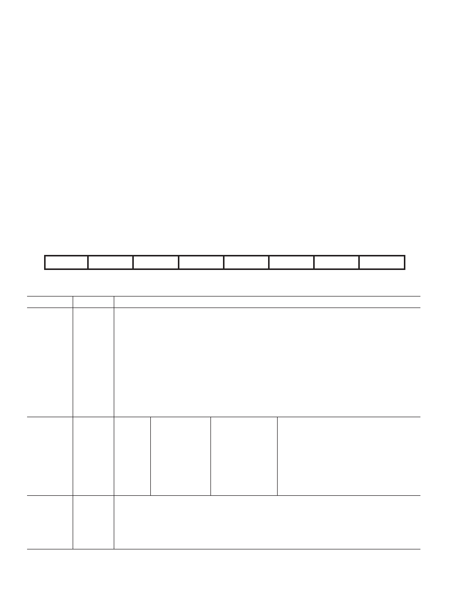
the bit designations for the main ADC control register. AD0CON7
through AD0CON0 indicate the bit location, AD0CON denoting
the bits are in the main ADC control register. AD0CON7 denotes
the first bit of the data stream. The number in parentheses
indicates the power-on/reset default status of that bit.
Table XIII. Main ADC Control Register (AD0CON) Bit Designations
Bit Location
Bit Name
Description
AD0CON7
AD0EN
Main ADC Enable Bit.
Set by user to enable the main ADC. When set, the main ADC operates according to the MD bits in
the mode register.
Cleared by the user to power down the Main ADC.
AD0CON6
WL
16-/24-Bit Operating Mode.
Set by user to enable 16-bit mode. The conversion results from the main ADC will be rounded to
16 bits and the main ADC data register will be 16 bits wide.
Cleared by user to enable 24-bit mode. The conversion results from the main ADC will be rounded to
24 bits and the main ADC data register will be 24 bits wide.
AD0CON5
CH1
Main ADC Channel Selection Bits.
AD0CON4
CH0
Written by the user to select the differential input pairs used by the main ADC as follows:
(Note: The CHCON bit resides in the Mode register.)
CHCON
CH1
CH0
Positive Input
Negative Input
Calibration Register Pair
00
0
AIN1
AIN2
0
00
1
AIN3
AIN4
1
01
0
AIN2
0
01
1
AIN3
AIN2
1
10
0
AIN1
AIN4
0
10
1
AIN3
AIN4
1
11
0
AIN4
0
11
1
AIN2
AIN4
2
AD0CON3
U/
B
Main ADC Unipolar/Bipolar Bit.
Set by user to enable unipolar coding, i.e., zero differential input will result in 0x00 0000 output and
a full-scale differential input will result in 0xFF FFFF output when operated in 24-bit mode.
Cleared by user to enable bipolar coding, Negative full-scale differential input will result in an output
code of 0x00 0000, zero differential input will result in an output code of 0x80 0000, and a
Positive full-scale differential input will result in an output code of 0xFF FFFF.
7
N
O
C
0
D
A6
N
O
C
0
D
A5
N
O
C
0
D
A4
N
O
C
0
D
A3
N
O
C
0
D
A2
N
O
C
0
D
A1
N
O
C
0
D
A0
N
O
C
0
D
A
)
0
(
N
E
0
D
A)
0
(
L
W)
0
(
1
H
C)
0
(
0
H
C/
U B
)
0
()
1
(
2
N
R)
1
(
1
N
R)
1
(
0
N
R
相关PDF资料 |
PDF描述 |
|---|---|
| HA1-4902-2 | IC COMPARATOR QUAD PREC 16-DIP |
| LTC1417IGN#PBF | IC A/D CONV 14BIT SAMPLNG 16SSOP |
| AD7732BRUZ | IC ADC 24BIT 2-CH 28-TSSOP |
| LTC1418CG#PBF | IC A/D CONV 14BIT SRL&PAR 28SSOP |
| AD7574JNZ | IC ADC 8BIT CMOS 5V 18-DIP |
相关代理商/技术参数 |
参数描述 |
|---|---|
| AD7719BRUZ-REEL | 功能描述:IC ADC 16BIT 24BIT DUAL 28TSSOP RoHS:是 类别:集成电路 (IC) >> 数据采集 - 模数转换器 系列:- 标准包装:1,000 系列:- 位数:12 采样率(每秒):300k 数据接口:并联 转换器数目:1 功率耗散(最大):75mW 电压电源:单电源 工作温度:0°C ~ 70°C 安装类型:表面贴装 封装/外壳:24-SOIC(0.295",7.50mm 宽) 供应商设备封装:24-SOIC 包装:带卷 (TR) 输入数目和类型:1 个单端,单极;1 个单端,双极 |
| AD7719BRUZ-REEL7 | 功能描述:IC ADC 16BIT 24BIT DUAL 28TSSOP RoHS:是 类别:集成电路 (IC) >> 数据采集 - 模数转换器 系列:- 标准包装:1,000 系列:- 位数:12 采样率(每秒):300k 数据接口:并联 转换器数目:1 功率耗散(最大):75mW 电压电源:单电源 工作温度:0°C ~ 70°C 安装类型:表面贴装 封装/外壳:24-SOIC(0.295",7.50mm 宽) 供应商设备封装:24-SOIC 包装:带卷 (TR) 输入数目和类型:1 个单端,单极;1 个单端,双极 |
| AD7719BRZ | 功能描述:IC ADC 16BIT 24BIT DUAL 28SOIC RoHS:是 类别:集成电路 (IC) >> 数据采集 - 模数转换器 系列:- 标准包装:1,000 系列:- 位数:12 采样率(每秒):300k 数据接口:并联 转换器数目:1 功率耗散(最大):75mW 电压电源:单电源 工作温度:0°C ~ 70°C 安装类型:表面贴装 封装/外壳:24-SOIC(0.295",7.50mm 宽) 供应商设备封装:24-SOIC 包装:带卷 (TR) 输入数目和类型:1 个单端,单极;1 个单端,双极 |
| AD7720 | 制造商:AD 制造商全称:Analog Devices 功能描述:CMOS Sigma-Delta Modulator |
| AD7720BRU | 功能描述:IC MODULATOR SIGMA-DELTA 28TSSOP RoHS:否 类别:集成电路 (IC) >> 数据采集 - 模数转换器 系列:- 标准包装:1,000 系列:- 位数:12 采样率(每秒):300k 数据接口:并联 转换器数目:1 功率耗散(最大):75mW 电压电源:单电源 工作温度:0°C ~ 70°C 安装类型:表面贴装 封装/外壳:24-SOIC(0.295",7.50mm 宽) 供应商设备封装:24-SOIC 包装:带卷 (TR) 输入数目和类型:1 个单端,单极;1 个单端,双极 |
发布紧急采购,3分钟左右您将得到回复。