- 您现在的位置:买卖IC网 > PDF目录10950 > ADAV801ASTZ (Analog Devices Inc)IC CODEC AUDIO R-DVD 3.3V 64LQFP PDF资料下载
参数资料
| 型号: | ADAV801ASTZ |
| 厂商: | Analog Devices Inc |
| 文件页数: | 18/60页 |
| 文件大小: | 0K |
| 描述: | IC CODEC AUDIO R-DVD 3.3V 64LQFP |
| 标准包装: | 1 |
| 类型: | 音频编解码器 |
| 数据接口: | 串行 |
| 分辨率(位): | 24 b |
| ADC / DAC 数量: | 2 / 2 |
| 三角积分调变: | 无 |
| 动态范围,标准 ADC / DAC (db): | 102 / 101 |
| 电压 - 电源,模拟: | 3 V ~ 3.6 V |
| 电压 - 电源,数字: | 3 V ~ 3.6 V |
| 工作温度: | -40°C ~ 85°C |
| 安装类型: | 表面贴装 |
| 封装/外壳: | 64-LQFP |
| 供应商设备封装: | 64-LQFP(10x10) |
| 包装: | 托盘 |
| 配用: | EVAL-ADAV801EBZ-ND - BOARD EVALUATION FOR ADAV801 |
第1页第2页第3页第4页第5页第6页第7页第8页第9页第10页第11页第12页第13页第14页第15页第16页第17页当前第18页第19页第20页第21页第22页第23页第24页第25页第26页第27页第28页第29页第30页第31页第32页第33页第34页第35页第36页第37页第38页第39页第40页第41页第42页第43页第44页第45页第46页第47页第48页第49页第50页第51页第52页第53页第54页第55页第56页第57页第58页第59页第60页
ADAV801
Rev. A | Page 25 of 60
Table 10. Professional Audio Standard
Data Bits
Address1
7
6
5
4
3
2
1
0
N
Sample
Frequency
Lock
Emphasis
Non-
Audio
Pro/Con
= 1
N + 1
User Bit Management
Channel Mode
N + 2
Alignment
Level
Source Word
Length
Use of Auxiliary Mode
Sample Bits
N + 3
Channel Identification
N + 4
fS
Scaling
Sample
Frequency (fS)
Reserved
Digital Audio
Reference
Signal
N + 5
Reserved
N + 6
Alphanumeric Channel Origin Data—First Character
N + 7
Alphanumeric Channel Origin Data
N + 8
Alphanumeric Channel Origin Data
N + 9
Alphanumeric Channel Origin Data—Last Character
N + 10
Alphanumeric Channel Destination Data—First Character
N + 11
Alphanumeric Channel Destination Data
N + 12
Alphanumeric Channel Destination Data
N + 13
Alphanumeric Channel Destination Data—Last Character
N + 14
Local Sample Address Code—LSW
N + 15
Local Sample Address Code
N + 16
Local Sample Address Code
N + 17
Local Sample Address Code—MSW
N + 18
Time of Day Code—LSW
N + 19
Time of Day Code
N + 20
Time of Day Code
N + 21
Time of Day Code—MSW
N + 22
Reliability Flags
Reserved
N + 23
Cyclic Redundancy Check Character (CRCC)
1 N = 0x20 for receiver channel status buffer.
N = 0x38 for transmitter channel status buffer.
The standards allow the channel status bits in each subframe to
be independent, but ordinarily the channel status bits in the two
subframes of each frame are the same. The channel status bits
are defined differently for the consumer audio standards and
the professional audio standards. The 192 channel status bits are
organized into 24 bytes and have the interpretations shown in
The S/PDIF transmitter and receiver have a comprehensive
register set. The registers give the user full access to the
functions of the S/PDIF block, such as detecting nonaudio and
validity bits, Q subcodes, and preambles. The channel status bits
as defined by the IEC60958 and AES3 specifications are stored
in register buffers for ease of use. An autobuffering function
allows channel status bits and user bits read by the receiver to be
copied directly to the transmitter block, removing the need for
user intervention.
Receiver Section
The ADAV801 uses a double-buffering scheme to handle read-
ing channel status and user bit information. The channel status
bits are available as a memory buffer, taking up 24 consecutive
register locations. The user bits are read using an indirect
memory addressing scheme, where the receiver user bit
indirect-address register is programmed with an offset to the
user bit buffer, and the receiver user bit data register can be read
to determine the user bits at that location. Reading the receiver
user bit data register automatically updates the indirect address
register to the next location in the buffer. Typically, the receiver
user bit indirect-address register is programmed to zero (the
start of the buffer), and the receiver user bit data register is read
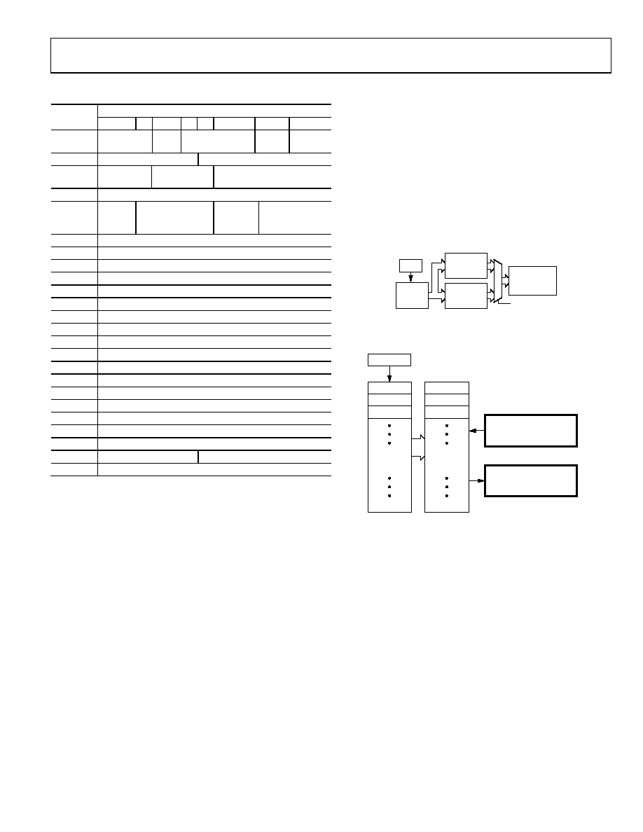
repeatedly until all the buffer’s data has been read. Figure 46
and Figure 47 show how receiving the channel status bits and
user bits is implemented.
04
57
7-
0
26
SECOND BUFFER
RECEIVE
CS BUFFER
(0x20 TO 0x37)
CHANNEL
STATUS A
(24 × 8 BITS)
CHANNEL
STATUS B
(24 × 8 BITS)
RxCSSWITCH
DIRIN
S/PDIF
RECEIVE
BUFFER
FIRST BUFFER
Figure 46. Channel Status Buffer
04
57
7-
0
27
S/PDIF
0...7
8...15
16...23
FIRST
BUFFER
0...7
8...15
16...23
USER-BIT
BUFFER
ADDRESS = 0x50
ADDRESS = 0x51
RECEIVER USER BIT
INDIRECT ADDRESS
REGISTER
RECEIVER USER BIT
DATA REGISTER
Figure 47. Receiver User Bit Buffer
The S/PDIF receive buffer is updated continuously by the
incoming S/PDIF stream. Once all the channel status bits for
the block (192 for Channel A and 192 for Channel B) are
received, the bits are copied into the receiver channel status
buffer. This buffer stores all 384 bits of channel status
information, and the RxCSSWITCH bit in the channel status
switch buffer register determines whether the Channel A or the
Channel B status bits are required to be read. The receive
channel status bit buffer is 24 bytes long and spans the address
range from 0x20 to 0x37.
Because the channel status bits of an S/PDIF stream rarely
change, a software interrupt/flag bit, RxCSBINT, is provided to
notify the host control either that a new block of channel status
bits is available or that the first five bytes of channel status
information have changed from a previous block. The function
of the RxCSBINT is controlled by the RxBCONF3 bit in the
Receiver Buffer Configuration register.
相关PDF资料 |
PDF描述 |
|---|---|
| MCIMX27LVOP4AR2 | IC LOW END I.MX27 404-MAPBGA |
| AD1938YSTZ | IC CODEC 24BIT 4ADC/8DAC 48LQFP |
| MC56F8335MFGE | IC DIGITAL SIGNAL CTLR 128-LQFP |
| MC9S12XHZ512CAG | IC MCU 16BIT 512 FLASH 144-LQFP |
| MC9S12C96MPBE | IC MCU 96K FLASH 4K RAM 52-LQFP |
相关代理商/技术参数 |
参数描述 |
|---|---|
| ADAV801ASTZ-REEL | 功能描述:IC CODEC AUDIO R-DVD 3.3V 64LQFP RoHS:是 类别:集成电路 (IC) >> 接口 - 编解码器 系列:- 标准包装:2,500 系列:- 类型:立体声音频 数据接口:串行 分辨率(位):18 b ADC / DAC 数量:2 / 2 三角积分调变:是 S/N 比,标准 ADC / DAC (db):81.5 / 88 动态范围,标准 ADC / DAC (db):82 / 87.5 电压 - 电源,模拟:2.6 V ~ 3.3 V 电压 - 电源,数字:1.7 V ~ 3.3 V 工作温度:-40°C ~ 85°C 安装类型:表面贴装 封装/外壳:48-WFQFN 裸露焊盘 供应商设备封装:48-TQFN-EP(7x7) 包装:带卷 (TR) |
| ADAV802AST | 制造商:Analog Devices 功能描述:AUDIO CODEC FOR RECORDABLE DVD - Bulk |
| ADAV802ASTZ | 制造商:Analog Devices 功能描述: |
| ADAV803 | 制造商:AD 制造商全称:Analog Devices 功能描述:Audio Codec for Recordable DVD |
| ADAV803AST | 制造商:Analog Devices 功能描述:AUDIO CODEC FOR RECORDABLE DVD - Bulk |
发布紧急采购,3分钟左右您将得到回复。