- 您现在的位置:买卖IC网 > PDF目录10950 > ADAV801ASTZ (Analog Devices Inc)IC CODEC AUDIO R-DVD 3.3V 64LQFP PDF资料下载
参数资料
| 型号: | ADAV801ASTZ |
| 厂商: | Analog Devices Inc |
| 文件页数: | 20/60页 |
| 文件大小: | 0K |
| 描述: | IC CODEC AUDIO R-DVD 3.3V 64LQFP |
| 标准包装: | 1 |
| 类型: | 音频编解码器 |
| 数据接口: | 串行 |
| 分辨率(位): | 24 b |
| ADC / DAC 数量: | 2 / 2 |
| 三角积分调变: | 无 |
| 动态范围,标准 ADC / DAC (db): | 102 / 101 |
| 电压 - 电源,模拟: | 3 V ~ 3.6 V |
| 电压 - 电源,数字: | 3 V ~ 3.6 V |
| 工作温度: | -40°C ~ 85°C |
| 安装类型: | 表面贴装 |
| 封装/外壳: | 64-LQFP |
| 供应商设备封装: | 64-LQFP(10x10) |
| 包装: | 托盘 |
| 配用: | EVAL-ADAV801EBZ-ND - BOARD EVALUATION FOR ADAV801 |
第1页第2页第3页第4页第5页第6页第7页第8页第9页第10页第11页第12页第13页第14页第15页第16页第17页第18页第19页当前第20页第21页第22页第23页第24页第25页第26页第27页第28页第29页第30页第31页第32页第33页第34页第35页第36页第37页第38页第39页第40页第41页第42页第43页第44页第45页第46页第47页第48页第49页第50页第51页第52页第53页第54页第55页第56页第57页第58页第59页第60页
ADAV801
Rev. A | Page 27 of 60
Table 15. Transmitter User Bit Buffer Size
TxBCONF0
Buffer Size
0
384 bits with Preamble Z as the start of the block.
1
768 bits with Preamble Z as the start of the block.
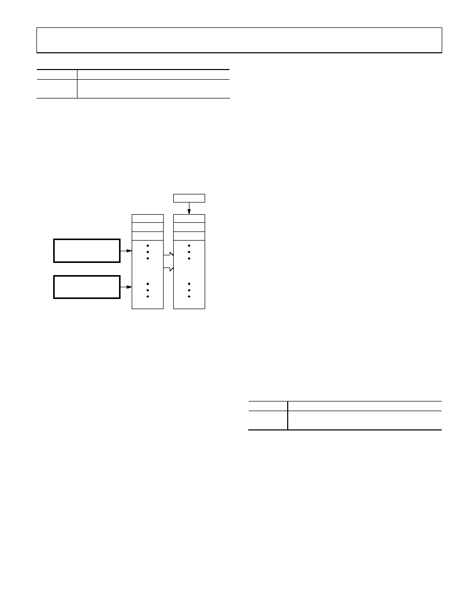
By using sticky bits and interrupts, the transmit buffers can
notify the host or microcontroller about their status. The sticky
bit, TxUBINT, is set when the transmit user bit buffer has been
updated and the second transmit user bit buffer is empty and
ready to accept new user bits. This bit is located in the interrupt
status register. When the host reads the interrupt status register,
this bit is cleared. Interrupts for the TxUBINT sticky bit can be
enabled by setting the TxUBINT Mask bit in the interrupt
status mask register
04
577
-02
9
S/PDIF 0
0...7
8...15
16...23
SECOND
BUFFER
0...7
8...15
16...23
USER-BIT
BUFFER
ADDRESS = 0x52
ADDRESS = 0x53
TRANSMITTER USER BIT
INDIRECT ADDRESS
REGISTER
TRANSMITTER USER BIT
DATA REGISTER
Figure 49. Transmitter User Bit Buffer
Autobuffering
The ADAV801 S/PDIF receiver and transmitter sections have
an autobuffering mode allowing the channel status and user bits
to be copied automatically from the receiver to the transmitter
without user intervention. The channel status and user bits
can be independently selected for autobuffering using the
Auto_CSBits and Auto_UBits bits, respectively, in the Auto-
buffer register. When the receiver and transmitter are running
at the same sample rate, the transmitted channel status and user
bits are the same as the received channel-status and user bits.
In many systems, however, it is likely that the receiver and
transmitter are not running at the same frequency. When the
transmitter sample rate is higher than receiver sample rate, the
channel status and user bit blocks are sometimes repeated.
When the transmitter sample rate is lower than the receiver
sample rate, the channel status and user bit blocks might be
dropped. Because the first five bytes of the channel status are
typically constant, they can be repeated or dropped with no
information loss. However, if the PRO bit in the channel status
is set and the local sample address code and time-of-day code
bytes contain information, these bytes might be repeated or
dropped, in which case information can be lost. It is up to the
user to determine how to handle this case.
When the user bits are transmitted according to the IEC 60958-3
format, the messages contained in the user bits can still be sent
without dropping or repeating messages. Because zero-stuffing
is allowed between IUs and messages, zeros can be added or
subtracted to preserve the messages. When the transmitter
sample rate is greater than the receiver sample rate, extra zeros
are stuffed between the messages. When the sample rate of the
transmitter is less than the sample rate of the receiver, the zeros
stuffed between the messages are subtracted. If there are not
enough zeros between the messages to be subtracted, the zeros
between IUs are subtracted as well. The Zero_Stuff_IU bit in
the Autobuffer register enables the adding or subtracting of
zeros between messages.
Interrupts
The ADAV801 provides interrupt bits to indicate the presence
of certain conditions that require attention. Reading the
interrupt status register (Register 0x1C) allows the user to
determine if any of the interrupts have been asserted. The bits
of the Interrupt Status register remain high, if set, until the
register is read. Two bits, SRCError and RxError, indicate
interrupt conditions in the sample rate converter and an S/PDIF
receiver error, respectively. Both these conditions require a read
of the appropriate error register (Register 0x1A and Register
0x18, respectively) to determine the exact cause of the interrupt.
Each interrupt in the interrupt status register has an associated
mask bit in the interrupt status mask register. The interrupt
mask bit must be set for the corresponding interrupt to be
generated. This feature allows the user to determine which
functions should be responded to.
The dual function pin ZEROL/INT can be set to indicate the
presence of no audio data on the left channel or the presence of
an interrupt set in the interrupt status register. As shown in
Table 16, the function of this pin is selected by the INTRPT bit
in DAC Control Register 4.
Table 16. ZEROL/INT Pin Functionality
INTRPT
Pin Functionality
0
Pin functions as a ZEROL flag pin.
1
Pin functions as an interrupt pin.
SERIAL DATA PORTS
The ADAV801 contains four flexible serial ports (SPORTs) to
allow data transfer to and from the codec. All four SPORTs are
independent and can be configured as master or slave ports. In
slave mode, the xLRCLK and xBCLK signals are inputs to the
serial ports. In master mode, the serial port generates the
xLRCLK and xBCLK signals. The master clock for the SPORT
can be selected from a number of sources, as shown in
相关PDF资料 |
PDF描述 |
|---|---|
| MCIMX27LVOP4AR2 | IC LOW END I.MX27 404-MAPBGA |
| AD1938YSTZ | IC CODEC 24BIT 4ADC/8DAC 48LQFP |
| MC56F8335MFGE | IC DIGITAL SIGNAL CTLR 128-LQFP |
| MC9S12XHZ512CAG | IC MCU 16BIT 512 FLASH 144-LQFP |
| MC9S12C96MPBE | IC MCU 96K FLASH 4K RAM 52-LQFP |
相关代理商/技术参数 |
参数描述 |
|---|---|
| ADAV801ASTZ-REEL | 功能描述:IC CODEC AUDIO R-DVD 3.3V 64LQFP RoHS:是 类别:集成电路 (IC) >> 接口 - 编解码器 系列:- 标准包装:2,500 系列:- 类型:立体声音频 数据接口:串行 分辨率(位):18 b ADC / DAC 数量:2 / 2 三角积分调变:是 S/N 比,标准 ADC / DAC (db):81.5 / 88 动态范围,标准 ADC / DAC (db):82 / 87.5 电压 - 电源,模拟:2.6 V ~ 3.3 V 电压 - 电源,数字:1.7 V ~ 3.3 V 工作温度:-40°C ~ 85°C 安装类型:表面贴装 封装/外壳:48-WFQFN 裸露焊盘 供应商设备封装:48-TQFN-EP(7x7) 包装:带卷 (TR) |
| ADAV802AST | 制造商:Analog Devices 功能描述:AUDIO CODEC FOR RECORDABLE DVD - Bulk |
| ADAV802ASTZ | 制造商:Analog Devices 功能描述: |
| ADAV803 | 制造商:AD 制造商全称:Analog Devices 功能描述:Audio Codec for Recordable DVD |
| ADAV803AST | 制造商:Analog Devices 功能描述:AUDIO CODEC FOR RECORDABLE DVD - Bulk |
发布紧急采购,3分钟左右您将得到回复。