- 您现在的位置:买卖IC网 > PDF目录1776 > ADP1829ACPZ-R7 (Analog Devices Inc)IC REG CTRLR BUCK PWM VM 32LFCSP PDF资料下载
参数资料
| 型号: | ADP1829ACPZ-R7 |
| 厂商: | Analog Devices Inc |
| 文件页数: | 22/28页 |
| 文件大小: | 0K |
| 描述: | IC REG CTRLR BUCK PWM VM 32LFCSP |
| 标准包装: | 1 |
| PWM 型: | 电压模式 |
| 输出数: | 2 |
| 频率 - 最大: | 720kHz |
| 占空比: | 93% |
| 电源电压: | 3 V ~ 20 V |
| 降压: | 是 |
| 升压: | 无 |
| 回扫: | 无 |
| 反相: | 无 |
| 倍增器: | 无 |
| 除法器: | 无 |
| Cuk: | 无 |
| 隔离: | 无 |
| 工作温度: | -40°C ~ 125°C |
| 封装/外壳: | 32-VFQFN 裸露焊盘,CSP |
| 包装: | 标准包装 |
| 产品目录页面: | 791 (CN2011-ZH PDF) |
| 配用: | ADP1829-EVALZ-ND - BOARD EVALUATION ADP1829 |
| 其它名称: | ADP1829ACPZ-R7DKR |
第1页第2页第3页第4页第5页第6页第7页第8页第9页第10页第11页第12页第13页第14页第15页第16页第17页第18页第19页第20页第21页当前第22页第23页第24页第25页第26页第27页第28页
�� �
�
�ADP1829�
�Data� Sheet�
�?�
�V� CSS� ?� 0� .� 8� V� ?� 1� ?� e� RC� SS�
�?�
�Because� of� the� finite� output� current� drive� of� the� error� amplifier,�
�C� I� needs� to� be� less� than� 10� nF.� If� it� is� larger� than� 10� nF,� choose� a�
�larger� R� TOP� and� recalculate� R� Z� and� C� I� until� C� I� is� less� than� 10� nF.�
�?�
�?�
�t�
�?�
�?�
�?�
�(48)�
�Because� C� HF� <<� C� I� ,� combining� Equation� 29� and� Equation� 39�
�yields�
�The� soft� start� period� ends� when� the� voltage� on� the� soft� start� pin�
�reaches� 0.6� V.� Substituting� 0.6� V� for� V� SS� and� solving� for� the�
�C� HF� ?�
�f� Z2� ?�
�?� ?�
�0� .� 6� V� ?� 0� .� 8� V� ?� 1� ?� e� 90� k� ?� C� SS� ?� ?�
�?�
�?�
�1�
�(44)�
�π� f� SW� R� Z�
�Next,� calculate� the� feedforward� capacitor,� C� FF.� .� Assume� R� FF� <<�
�R� TOP� ,� then� Equation� 28� is� simplified� to�
�1�
�(45)�
�2� π� C� FF� R� TOP�
�Solving� C� FF� in� Equation� 45� yields�
�number� of� RC� time� constants,�
�t� SS�
�?� ?�
�t� SS� ?� 1� .� 386� RC� SS�
�Because� R� =� 90� kΩ,�
�C� SS� ?� t� SS� ?� 8� μF/� sec�
�(49)�
�(50)�
�(51)�
�C� FF� ?�
�1�
�2� π� R� TOP� f� Z2�
�(46)�
�where� t� SS� is� the� desired� soft� start� time� in� seconds.�
�VOLTAGE� TRACKING�
�where� f� Z2� is� obtained� from� Equation� 40� or� Equation� 41.�
�The� feedforward� resistor,� R� FF� ,� can� be� calculated� by� combining�
�Equation� 30� and� Equation� 39�
�The� ADP1829� includes� a� tracking� feature� that� prevents� an�
�output� voltage� from� exceeding� a� master� voltage.� This� is�
�especially� important� when� the� ADP1829� is� powering� separate�
�power� supply� voltages� on� a� single� integrated� circuit,� such� as� the�
�R� FF� ?�
�1�
�π� C� FF� f� SW�
�(47)�
�core� and� I/O� voltages� of� a� DSP� or� microcontroller.� In� these�
�cases,� improper� sequencing� can� cause� damage� to� the� load.�
�Check� that� the� calculated� component� values� are� reasonable.� For�
�instance,� capacitors� smaller� than� about� 10� pF� should� be� avoided.�
�In� addition,� the� ADP1829� error� amplifier� has� finite� output�
�current� drive,� so� R� Z� values� less� than� 3� k� and� C� I� values� greater�
�than� 10� nF� should� be� avoided.� If� necessary,� recalculate� the�
�compensation� network� with� a� different� starting� value� of� R� TOP� .�
�If� R� Z� is� too� small� and� C� I� is� too� big,� start� with� a� larger� value� of� R� TOP� .�
�This� compensation� technique� should� yield� a� good� working�
�solution.�
�In� general,� aluminum� electrolytic� capacitors� have� high� ESR,� and�
�a� Type� II� compensation� is� adequate.� However,� if� several� aluminum�
�electrolytic� capacitors� are� connected� in� parallel,� producing� a� low�
�effective� ESR,� then� Type� III� compensation� is� needed.� In� addition,�
�ceramic� capacitors� have� very� low� ESR,� in� the� order� of� a� few�
�milliohms.� Type� III� compensation� is� needed� for� ceramic� output�
�capacitors.� Type� III� compensation� offers� better� performance�
�than� Type� II� in� terms� of� more� low� frequency� gain� and� more�
�phase� margin� and� less� high� frequency� gain� at� the� cross-over�
�frequency.�
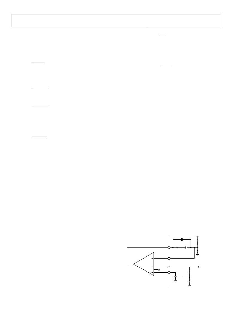
�The� ADP1829� tracking� input� is� an� additional� positive� input� to�
�the� error� amplifier.� The� feedback� voltage� is� regulated� to� the� lower� of�
�the� 0.6� V� reference� or� the� voltage� at� TRK,� so� a� lower� voltage� on�
�TRK� limits� the� output� voltage.� This� feature� allows� implementation�
�of� two� different� types� of� tracking:� coincident� tracking,� where�
�the� output� voltage� is� the� same� as� the� master� voltage� until� the�
�master� voltage� reaches� regulation,� or� ratiometric� tracking,� where�
�the� output� voltage� is� limited� to� a� fraction� of� the� master� voltage.�
�In� all� tracking� configurations,� the� master� voltage� should� be�
�higher� than� the� slave� voltage.�
�Note� that� the� soft� start� time� setting� of� the� master� voltage� should�
�be� longer� than� the� soft� start� of� the� slave� voltage.� This� forces� the�
�rise� time� of� the� master� voltage� to� be� imposed� on� the� slave� voltage.�
�If� the� soft� start� setting� of� the� slave� voltage� is� longer,� the� slave�
�comes� up� more� slowly� and� the� tracking� relationship� is� not� seen�
�at� the� output.� The� slave� channel� should� still� have� a� soft� start�
�capacitor� to� give� a� small� but� reasonable� soft� start� time� to� protect�
�in� case� of� restart� after� a� current-limit� event.�
�V� OUT�
�For� a� more� exact� method� or� to� optimize� for� other� system�
�characteristics,� a� number� of� references� and� tools� are� available�
�COMP�
�R� TOP�
�from� your� Analog� Devices,� Inc.� applications� support� team.�
�SOFT� START�
�FB�
�R� BOT�
�The� ADP1829� uses� an� adjustable� soft� start� to� limit� the� output�
�voltage� ramp-up� period,� thus� limiting� the� input� inrush� current.�
�The� soft� start� is� set� by� selecting� the� capacitor,� C� SS� ,� from� SS1� and�
�SS2� to� GND.� The� ADP1829� charges� C� SS� to� 0.8� V� through� an�
�internal� 90� k� resistor.� The� voltage� on� the� soft� start� capacitor�
�ERROR�
�AMPLIFIER�
�TRK�
�0.6V�
�SS�
�DETAIL� VIEW� OF�
�R� TRKT�
�R� TRKB�
�MASTER�
�VOLTAGE�
�while� it� is� charging� is�
�Rev.� C� |� Page� 22� of� 28�
�ADP1829�
�Figure� 30.� Voltage� Tracking�
�相关PDF资料 |
PDF描述 |
|---|---|
| ADP1850ACPZ-R7 | IC REG CTRLR BUCK PWM CM 32LFCSP |
| ADP1864AUJZ-R7 | IC REG CTRLR BUCK PWM TSOT23-6 |
| ADP1871ACPZ-0.6-R7 | IC REG CTRLR BUCK PWM CM 10LFCSP |
| ADP1873ARMZ-0.3-R7 | IC REG CTRLR BUCK PWM CM 10-MSOP |
| ADP1875ARQZ-0.3-R7 | IC REG CTRLR BUCK PWM CM 16-QSOP |
相关代理商/技术参数 |
参数描述 |
|---|---|
| ADP1829-BL1-EVZ | 制造商:Analog Devices 功能描述:BLANK ADISIMPOWER EVAL ADP1829 - Boxed Product (Development Kits) |
| ADP1829-BL2-EVZ | 制造商:Analog Devices 功能描述:Evaluation Board For Dual Interleaved Step-Down DC-To-DC Controller With Tracking 制造商:Analog Devices 功能描述:BLANK ADISIMPOWER EVAL ADP1829 - Boxed Product (Development Kits) |
| ADP1829-EVALZ | 功能描述:BOARD EVALUATION ADP1829 RoHS:是 类别:编程器,开发系统 >> 评估板 - DC/DC 与 AC/DC(离线)SMPS 系列:- 产品培训模块:Obsolescence Mitigation Program 标准包装:1 系列:True Shutdown™ 主要目的:DC/DC,步升 输出及类型:1,非隔离 功率 - 输出:- 输出电压:- 电流 - 输出:1A 输入电压:2.5 V ~ 5.5 V 稳压器拓扑结构:升压 频率 - 开关:3MHz 板类型:完全填充 已供物品:板 已用 IC / 零件:MAX8969 |
| ADP1850 | 制造商:AD 制造商全称:Analog Devices 功能描述:Wide Range Input, Dual/Two-Phase, DC-to-DC Synchronous Buck Controller |
| ADP1850ACPZ | 制造商:Analog Devices 功能描述:IC BUCK CNTRL SYNC 2PH 32LFCSP |
发布紧急采购,3分钟左右您将得到回复。