参数资料
| 型号: | ADUC836BCPZ |
| 厂商: | Analog Devices Inc |
| 文件页数: | 55/80页 |
| 文件大小: | 0K |
| 描述: | IC MCU 62K FLASH ADC/DAC 56LFCSP |
| 标准包装: | 1 |
| 系列: | MicroConverter® ADuC8xx |
| 核心处理器: | 8052 |
| 芯体尺寸: | 8-位 |
| 速度: | 12.58MHz |
| 连通性: | EBI/EMI,I²C,SPI,UART/USART |
| 外围设备: | POR,PSM,PWM,温度传感器,WDT |
| 输入/输出数: | 34 |
| 程序存储器容量: | 62KB(62K x 8) |
| 程序存储器类型: | 闪存 |
| EEPROM 大小: | 4K x 8 |
| RAM 容量: | 2.25K x 8 |
| 电压 - 电源 (Vcc/Vdd): | 2.7 V ~ 5.25 V |
| 数据转换器: | A/D 7x16b; D/A 1x12b |
| 振荡器型: | 内部 |
| 工作温度: | -40°C ~ 85°C |
| 封装/外壳: | 56-VFQFN 裸露焊盘,CSP |
| 包装: | 托盘 |
第1页第2页第3页第4页第5页第6页第7页第8页第9页第10页第11页第12页第13页第14页第15页第16页第17页第18页第19页第20页第21页第22页第23页第24页第25页第26页第27页第28页第29页第30页第31页第32页第33页第34页第35页第36页第37页第38页第39页第40页第41页第42页第43页第44页第45页第46页第47页第48页第49页第50页第51页第52页第53页第54页当前第55页第56页第57页第58页第59页第60页第61页第62页第63页第64页第65页第66页第67页第68页第69页第70页第71页第72页第73页第74页第75页第76页第77页第78页第79页第80页
ADuC836
–58–
ADuC836
–59–
Timer 2 Generated Baud Rates
Baud rates can also be generated using Timer 2. Using Timer 2 is
similar to using Timer 1 in that the timer must overflow 16 times
before a bit is transmitted/received. Because Timer 2 has a 16-bit
Autoreload mode, a wider range of baud rates is possible.
Mode 1
3
and Mode Baud Rate
Timer Overflow Rate
=
( ) × (
)
1 16
2
Therefore when Timer 2 is used to generate baud rates, the timer
increments every two clock cycles and not every core machine
cycle as before.Thus, it increments six times faster than Timer 1,
and therefore baud rates six times faster are possible. Because
Timer 2 has a 16-bit autoreload capability, very low baud rates
are still possible.
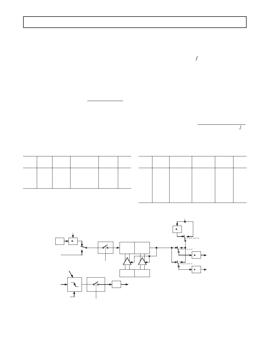
Timer 2 is selected as the baud rate generator by setting the TCLK
and/or RCLK in T2CON.The baud rates for transmit and receive
can be simultaneously different. Setting RCLK and/or TCLK puts
Timer 2 into its baud rate generator mode, as shown in Figure 56.
In this case, the baud rate is given by the formula:
Mode 1
3
and Mode Baud Rate
f
RCAP H L
CORE
=
×
(
)
32
65536
2
Table XXXII shows some commonly used baud rates and
how they might be calculated from a core clock frequency of
1.5728 MHz and 12.5829 MHz using Timer 2.
Table XXXII. Commonly Used Baud Rates,Timer 2
Ideal
Core
RCAP2H
RCAP2L
Actual
%
Baud
CLK
Value
Baud
Error
19200
12.58
–1 (FFH)
–20 (ECH)
19661
2.4
9600
12.58
–1 (FFH)
–41 (D7H)
9591
0.1
1600
12.58
–1 (FFH)
–164 (5CH) 2398
0.1
1200
12.58
–2 (FEH)
–72 (B8H)
1199
0.1
9600
1.57
–1 (FFH)
–5 (FBH)
9830
2.4
1600
1.57
–1 (FFH)
–20 (ECH)
1658
2.4
1200
1.57
–1 (FFH)
–41 (D7H)
1199
0.1
BAUD RATE GENERATION USING TIMER 1 AND TIMER 2
Timer 1 Generated Baud Rates
When Timer 1 is used as the baud rate generator, the baud rates
in Modes 1 and 3 are determined by the Timer 1 overflow rate
and the value of SMOD as follows:
Modes 1
3
1
and Baud Rate
Timer Overflow Rate
SMOD
=
(
)×(
)
2
32
The Timer 1 interrupt should be disabled in this application.
The timer itself can be configured for either timer or counter
operation, and in any of its three running modes. In the most
typical application, it is configured for timer operation, in the
Autoreload mode (high nibble of TMOD = 0100 binary). In this
case, the baud rate is given by the formula:
Mode 1
3
1
and Mode Baud Rate
f
TH
SMOD
CORE
=
×
(
)
2
32 12 256
A very low baud rate can also be achieved with Timer 1 by leaving
the Timer 1 interrupt enabled, configuring the timer to run as a
16-bit timer (high nibble of TMOD = 0100 binary), and using
the Timer 1 interrupt to do a 16-bit software reload.Table XXXI
shows some commonly used baud rates and how they might
be calculated from a core clock frequency of 1.5728 MHz and
12.58 MHz using Timer 1. Generally speaking, a 5% error is
tolerable using asynchronous (start/stop) communications.
Table XXXI. Commonly Used Baud Rates,Timer 1
Ideal
Core
SMOD
TH1-Reload
Actual
%
Baud
CLK
Value
Baud
Error
9600
12.58
1
–7 (F9H)
9362
2.5
1600
12.58
1
–27 (E5H)
1627
1.1
1200
12.58
1
–55 (C9H)
1192
0.7
1200
1.57
1
–7 (F9H)
1170
2.5
CORE
CLK*
2
T2
PIN
TR2
CONTROL
TL2
(8 BITS)
TH2
(8 BITS)
RELOAD
EXEN2
CONTROL
T2EX
PIN
TRANSITION
DETECTOR
EXF 2
TIMER 2
INTERRUPT
NOTE AVAILABILITY OF ADDITIONAL
EXTERNAL INTERRUPT
*THE CORE CLOCK IS THE OUTPUT OF THE PLL (SEE THE ON-CHIP PLL SECTION)
RCAP2L
RCAP2H
TIMER 2
OVERFLOW
2
16
RCLK
TCLK
RX
CLOCK
TX
CLOCK
0
1
0
SMOD
TIMER 1
OVERFLOW
C/T2 = 0
C/T2 = 1
OSC. FREQ. IS DIVIDED BY 2, NOT 12.
Figure 56.Timer 2, UART Baud Rates
REV. A
相关PDF资料 |
PDF描述 |
|---|---|
| ADUC843BSZ62-5 | IC ADC 12BIT W/FLASH MCU 52-MQFP |
| ADUC845BCPZ62-5 | IC FLASH MCU W/24BIT ADC 56-CSP |
| ADUC847BCPZ62-5 | IC MCU FLASH W/24BIT ADC 56-CSP |
| ADV202BBCZ-135 | IC CODEC VIDEO 135MHZ 144CSPBGA |
| ADV212BBCZ-115 | IC CODEC VID JPEG 2000 121CSPBGA |
相关代理商/技术参数 |
参数描述 |
|---|---|
| ADUC836BCPZ-REEL | 功能描述:IC MCU 62K FLASH ADC/DAC 56LFCSP RoHS:是 类别:集成电路 (IC) >> 嵌入式 - 微控制器, 系列:MicroConverter® ADuC8xx 标准包装:38 系列:Encore!® XP® 核心处理器:eZ8 芯体尺寸:8-位 速度:5MHz 连通性:IrDA,UART/USART 外围设备:欠压检测/复位,LED,POR,PWM,WDT 输入/输出数:16 程序存储器容量:4KB(4K x 8) 程序存储器类型:闪存 EEPROM 大小:- RAM 容量:1K x 8 电压 - 电源 (Vcc/Vdd):2.7 V ~ 3.6 V 数据转换器:- 振荡器型:内部 工作温度:-40°C ~ 105°C 封装/外壳:20-SOIC(0.295",7.50mm 宽) 包装:管件 其它名称:269-4116Z8F0413SH005EG-ND |
| ADUC836BS | 制造商:Analog Devices 功能描述:MCU 8-bit ADuC8xx 8052 CISC 62KB Flash 3.3V/5V 52-Pin MQFP 制造商:Analog Devices 功能描述:8BIT MCU +16BIT DUAL ADC MQFP52 |
| ADUC836BS | 制造商:Analog Devices 功能描述:IC SEMICONDUCTOR ((NS)) |
| ADUC836BSZ | 功能描述:IC ADC DUAL 16BIT W/MCU 52-MQFP RoHS:是 类别:集成电路 (IC) >> 嵌入式 - 微控制器, 系列:MicroConverter® ADuC8xx 标准包装:250 系列:56F8xxx 核心处理器:56800E 芯体尺寸:16-位 速度:60MHz 连通性:CAN,SCI,SPI 外围设备:POR,PWM,温度传感器,WDT 输入/输出数:21 程序存储器容量:40KB(20K x 16) 程序存储器类型:闪存 EEPROM 大小:- RAM 容量:6K x 16 电压 - 电源 (Vcc/Vdd):2.25 V ~ 3.6 V 数据转换器:A/D 6x12b 振荡器型:内部 工作温度:-40°C ~ 125°C 封装/外壳:48-LQFP 包装:托盘 配用:MC56F8323EVME-ND - BOARD EVALUATION MC56F8323 |
| ADUC841 | 制造商:AD 制造商全称:Analog Devices 功能描述:MicroConverter 12-Bit ADCs and DACs with Embedded High Speed 62-kB Flash MCU |
发布紧急采购,3分钟左右您将得到回复。