- 您现在的位置:买卖IC网 > PDF目录16409 > AMIS30623C6238G (ON Semiconductor)IC MOTOR DRIVER/CTLR 20-SOIC PDF资料下载
参数资料
| 型号: | AMIS30623C6238G |
| 厂商: | ON Semiconductor |
| 文件页数: | 37/61页 |
| 文件大小: | 0K |
| 描述: | IC MOTOR DRIVER/CTLR 20-SOIC |
| 标准包装: | 38 |
| 应用: | 步进电机驱动器 |
| 评估套件: | 可供 |
| 输出数: | 1 |
| 电流 - 输出: | 800mA |
| 电源电压: | 6.5 V ~ 29 V |
| 工作温度: | -40°C ~ 165°C |
| 安装类型: | 表面贴装 |
| 封装/外壳: | 20-SOIC(0.295",7.50mm 宽) |
| 供应商设备封装: | 20-SOIC |
| 包装: | 管件 |
第1页第2页第3页第4页第5页第6页第7页第8页第9页第10页第11页第12页第13页第14页第15页第16页第17页第18页第19页第20页第21页第22页第23页第24页第25页第26页第27页第28页第29页第30页第31页第32页第33页第34页第35页第36页当前第37页第38页第39页第40页第41页第42页第43页第44页第45页第46页第47页第48页第49页第50页第51页第52页第53页第54页第55页第56页第57页第58页第59页第60页第61页
�� �
�
�AMIS� ?� 30623�
�With:�
�Data� error� flag:� (=� Checksum� error� +� StopBit� error� +� Length�
�error)�
�Header� error� flag:� (=� Parity� error� +� SynchField� error)�
�Time� out� flag:� The� message� frame� is� not� fully� completed�
�within� the� maximum� length�
�Bit� error� flag:� Difference� in� bit� sent� and� bit� monitored� on� the�
�LIN� bus�
�A� GetFullStatus� frame� will� reset� the� error� status� register.�
�Physical� Address� of� the� Circuit�
�The� circuit� must� be� provided� with� a� physical� address� in� order�
�to� discriminate� this� circuit� from� other� ones� on� the� LIN� bus.� This�
�address� is� coded� on� 7� bits,� yielding� the� theoretical� possibility�
�of� 128� different� circuits� on� the� same� bus.� It� is� a� combination� of�
�4� OTP� memory� bits� and� of� the� 3� hardwired� address� bits� (pins�
�HW[2:0]).� However� the� maximum� number� of� nodes� in� a� LIN�
�network� is� also� limited� by� the� physical� properties� of� the� bus�
�line.� It� is� recommended� to� limit� the� number� of� nodes� in� a� LIN�
�network� to� not� exceed� 16.� Otherwise� the� reduced� network�
�impedance� may� prohibit� a� fault� free� communication� under�
�worst� case� conditions.� Every� additional� node� lowers� the�
�network� impedance� by� approximately� 3%.�
�AD6� AD5� AD4� AD3� AD2� AD1� AD0� Physical� address�
�↑� ↑� ↑� PA3� PA2� PA1� PA0� OTP� memory�
�HW0� HW1� HW2� Hardwired� bits�
�NOTE:� Pins� HW0� and� HW1� are� 5� V� digital� inputs,� whereas� pin�
�HW2� is� compliant� with� a� 12� V� level,� e.g.� it� can� be�
�connected� to� Vbat� or� Gnd� via� a� terminal� of� the� PCB.� For�
�SetPositionShort� it� is� recommended� to� set� HW0,� HW1�
�and� HW2� to� ’1’.�
�LIN� Frames�
�The� LIN� frames� can� be� divided� in� writing� and� reading�
�frames.� A� frame� is� composed� of� an� 8� ?� bit� Identifier� followed�
�by� 2,� 4� or� 8� data� ?� bytes� and� a� checksum� byte.�
�Note:� The� checksum� is� conform� LIN1.3,� classic� checksum�
�calculation� over� only� data� bytes.� (Checksum� is� an� inverted�
�8� ?� bit� sum� with� carry� over� all� data� bytes.)�
�Writing� frames� will� be� used� to:�
�?� Program� the� OTP� Memory;�
�?� Configure� the� component� with� the� stepper� ?� motor�
�parameters� (current,� speed,� stepping� ?� mode,� etc.);�
�?� Provide� set� ?� point� position� for� the� stepper� ?� motor;�
�?� Control� the� motion� state� machine.�
�Whereas� reading� frames� will� be� used� to:�
�?� Get� the� actual� position� of� the� stepper� ?� motor;�
�?� Get� status� information� such� as� error� flags;�
�?� Verify� the� right� programming� and� configuration� of� the�
�component.�
�Writing� Frames�
�The� LIN� master� sends� commands� and/or� information� to�
�the� slave� nodes� by� means� of� a� writing� frame.� According� to�
�the� LIN� specification,� identifiers� are� to� be� used� to� determine�
�a� specific� action.� If� a� physical� addressing� is� needed,� then�
�some� bits� of� the� data� field� can� be� dedicated� to� this,� as�
�illustrated� in� the� example� below.�
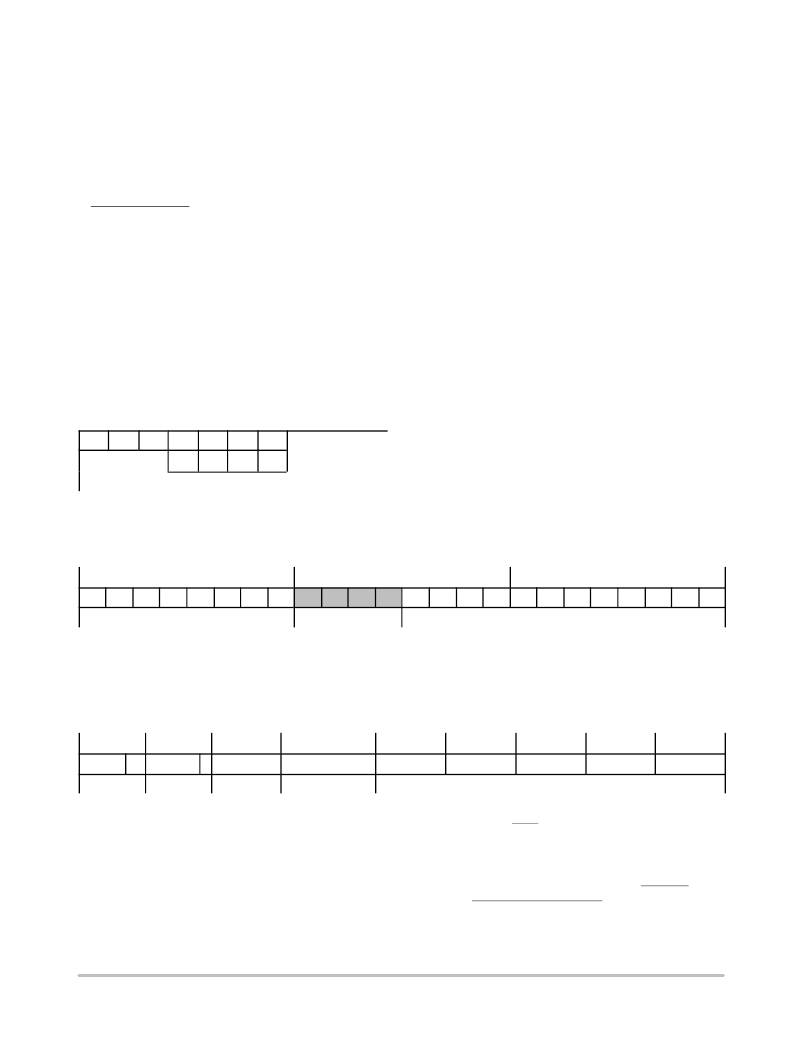
�Identifier� Byte�
�Data� Byte� 1�
�Data� Byte� 2�
�ID0�
�ID1�
�ID2�
�ID3�
�ID4�
�ID5�
�ID6�
�ID7�
�phys.� address�
�<ID6>� and� <ID7>� are� used� for� parity� check� over� <ID0>�
�to� <ID5>,� conform� LIN1.3� specification.� <ID6>� =� <ID0>� ?�
�<ID1>� ?� <ID2>� ?� <ID4>� (even� parity)� and� <ID7>� =�
�NOT(<ID1>� ?� <ID3>� ?� <ID4>� ?� <ID5>)� (odd� parity).�
�command� parameters� (e.g.� position)�
�Another� possibility� is� to� determine� the� specific� action�
�within� the� data� field� in� order� to� use� less� identifiers.� One� can�
�for� example� use� the� reserved� identifier� 0x3C� and� take�
�advantage� of� the� 8� byte� data� field� to� provide� a� physical�
�address,� a� command� and� the� needed� parameters� for� the�
�action,� as� illustrated� in� the� example� below.�
�ID�
�Data� Byte� 1�
�Data� Byte� 2�
�Data� Byte� 3�
�Data� Byte� 4�
�Data� Byte� 5�
�Data� Byte� 6�
�Data� Byte� 7�
�Data� Byte� 8�
�0x3C�
�00�
�1�
�AppCmd�
�command�
�physical� address�
�parameters�
�NOTE:�
�Bit� 7� of� Data� byte� 1� must� be� at� ‘1’� since� the� LIN� specification� requires� that� contents� from� 0x00� to� 0x7F� must� be� reserved� for�
�broadcast� messages� (0x00� being� for� the� “Sleep”� message).� See� also� LIN� command� Sleep�
�The� writing� frames� used� with� the� AMIS� ?� 30623� are� the�
�following:�
�Type� #1:� General� purpose� 2� or� 4� data� bytes� writing�
�frame� with� a� dynamically� assigned� identifier.�
�This� type� is� dedicated� to� short� writing� actions�
�when� the� bus� load� can� be� an� issue.� They� are�
�used� to� provide� direct� command� to� one�
�(� <Broad>� =� ‘1’)� or� all� the� slave� nodes�
�http://onsemi.com�
�37�
�(� <Broad>� =� ‘0’).� If� <Broad>� =� ‘1’,� the�
�physical� address� of� the� slave� node� is� provided�
�by� the� 7� remaining� bits� of� DATA2.� DATA1� will�
�contain� the� command� code� (see� Dynamic�
�assignment� of� Identifiers),� while,� if� present,�
�DATA3� to� DATA4� will� contain� the� command�
�parameters,� as� shown� below.�
�相关PDF资料 |
PDF描述 |
|---|---|
| UPM0J152MHD6TO | CAP ALUM 1500UF 6.3V 20% RADIAL |
| 012361-000 | SHIELD TERMINATOR SOLDER SLEEVE |
| VE-24Z-EV | CONVERTER MOD DC/DC 2V 60W |
| 1331-562K | INDUCTOR SHIELDED 5.60UH SMD |
| 573687-000 | SHIELD TERMINATOR |
相关代理商/技术参数 |
参数描述 |
|---|---|
| AMIS30623C6238RG | 功能描述:马达/运动/点火控制器和驱动器 LIN STEPPER DRIVER STALL RoHS:否 制造商:STMicroelectronics 产品:Stepper Motor Controllers / Drivers 类型:2 Phase Stepper Motor Driver 工作电源电压:8 V to 45 V 电源电流:0.5 mA 工作温度:- 25 C to + 125 C 安装风格:SMD/SMT 封装 / 箱体:HTSSOP-28 封装:Tube |
| AMIS30623C6239G | 功能描述:马达/运动/点火控制器和驱动器 LIN 800mA STEPPER DRIVER RoHS:否 制造商:STMicroelectronics 产品:Stepper Motor Controllers / Drivers 类型:2 Phase Stepper Motor Driver 工作电源电压:8 V to 45 V 电源电流:0.5 mA 工作温度:- 25 C to + 125 C 安装风格:SMD/SMT 封装 / 箱体:HTSSOP-28 封装:Tube |
| AMIS30623C6239RG | 功能描述:马达/运动/点火控制器和驱动器 LIN 800mA STEPPER DRIVER RoHS:否 制造商:STMicroelectronics 产品:Stepper Motor Controllers / Drivers 类型:2 Phase Stepper Motor Driver 工作电源电压:8 V to 45 V 电源电流:0.5 mA 工作温度:- 25 C to + 125 C 安装风格:SMD/SMT 封装 / 箱体:HTSSOP-28 封装:Tube |
| AMIS30623C623AG | 功能描述:马达/运动/点火控制器和驱动器 LIN 800mA STEPPER DRIVER RoHS:否 制造商:STMicroelectronics 产品:Stepper Motor Controllers / Drivers 类型:2 Phase Stepper Motor Driver 工作电源电压:8 V to 45 V 电源电流:0.5 mA 工作温度:- 25 C to + 125 C 安装风格:SMD/SMT 封装 / 箱体:HTSSOP-28 封装:Tube |
| AMIS30623C623ARG | 功能描述:马达/运动/点火控制器和驱动器 800mA CNTRL LIN BUS MICRO STP/STALL DET RoHS:否 制造商:STMicroelectronics 产品:Stepper Motor Controllers / Drivers 类型:2 Phase Stepper Motor Driver 工作电源电压:8 V to 45 V 电源电流:0.5 mA 工作温度:- 25 C to + 125 C 安装风格:SMD/SMT 封装 / 箱体:HTSSOP-28 封装:Tube |
发布紧急采购,3分钟左右您将得到回复。