- 您现在的位置:买卖IC网 > PDF目录295335 > CS5165GDWR16 (ON SEMICONDUCTOR) 1.5 A SWITCHING CONTROLLER, 1000 kHz SWITCHING FREQ-MAX, PDSO16 PDF资料下载
参数资料
| 型号: | CS5165GDWR16 |
| 厂商: | ON SEMICONDUCTOR |
| 元件分类: | 稳压器 |
| 英文描述: | 1.5 A SWITCHING CONTROLLER, 1000 kHz SWITCHING FREQ-MAX, PDSO16 |
| 封装: | SOIC-16 |
| 文件页数: | 8/21页 |
| 文件大小: | 718K |
| 代理商: | CS5165GDWR16 |
CS5165
http://onsemi.com
16
It is therefore required that the output voltage attains an
out of regulation or in regulation level for at least the builtin
delay time duration before the Power Good signal can
change state.
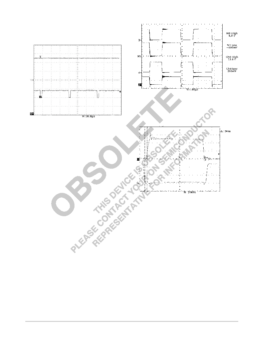
Figure 25. Power Good is Insensitive to Out of
Regulation Conditions that are Present for a
Duration Less Than the Built In Delay
Trace 4 VFB (1.0 V/div.)
Trace 2 PWRGD (2.0 V/div.)
Selecting External Components
The CS5165 buck regulator can be used with a wide range
of external power components to optimize the cost and
performance of a particular design. The following
information can be used as general guidelines to assist in
their selection.
NFET Power Transistors
Both logic level and standard FETs can be used. The
reference designs derive gate drive from the 12 V supply
which is generally available in most computer systems and
utilize logic level FETs. A charge pump may be easily
implemented to support 5.0 V only systems. Multiple FET’s
may be paralleled to reduce losses and improve efficiency
and thermal management.
Voltage applied to the FET gates depends on the
application circuit used. Both upper and lower gate driver
outputs are specified to drive to within 1.5 V of ground when
in the low state and to within 2.0 V of their respective bias
supplies when in the high state. In practice, the FET gates
will be driven rail to rail due to overshoot caused by the
capacitive load they present to the controller IC. For the
typical application where VCC = 12 V and 5.0 V is used as
the source for the regulator output current, the following
gate drive is provided:
VGS(BOTTOM) + 12 V
VGS(TOP) + 12 V * 5.0 V + 7.0 V
(see Figure 26)
Figure 26. Gate Drive Waveforms Depicting
Rail to Rail Swing
Trace 3 GATE(H) (10 V/div.)
Trace 1 GATE(H) 5.0 VIN
Trace 4 GATE(L) (10 V/div.)
Trace 2 Inductor Switching Node (5.0 V/div.)
Figure 27. Normal Operation Showing the Guaranteed
NonOverlap Time Between the High and LowSide
MOSFET Gate Drives, ILOAD = 14 A
Trace 1 = GATE(H) (5.0 V/div.)
Trace 2 = GATE(L) (5.0 V/div.)
@ 2.2 V
The CS5165 provides adaptive control of the external
NFET conduction times by guaranteeing a typical 65 ns
nonoverlap between the upper and lower MOSFET gate
drive pulses. This feature eliminates the potentially
catastrophic effect of “shootthrough current”, a condition
during which both FETs conduct causing them to overheat,
selfdestruct, and possibly inflict irreversible damage to the
processor.
The most important aspect of FET performance is
RDSON, which effects regulator efficiency and FET thermal
management requirements.
The power dissipated by the MOSFETs may be estimated
as follows:
Switching MOSFET:
相关PDF资料 |
PDF描述 |
|---|---|
| CS5332GDW28 | 1.5 A SWITCHING CONTROLLER, 1000 kHz SWITCHING FREQ-MAX, PDSO28 |
| CS600/L2 | 1 CHANNEL LOGIC OUTPUT OPTOCOUPLER |
| CSBLA384KECE-B0 | CERAMIC RESONATOR, 0.384 MHz |
| CSC5026-0102F | 16 CONTACT(S), COMBINATION LINE CONNECTOR, SOCKET |
| CSD10030 | ZERO RECOVERY RECTIFIER |
相关代理商/技术参数 |
参数描述 |
|---|---|
| CS-5165HDW16 | 制造商:未知厂家 制造商全称:未知厂家 功能描述:Voltage-Mode SMPS Controller |
| CS-5165HDWR16 | 制造商:未知厂家 制造商全称:未知厂家 功能描述:Voltage-Mode SMPS Controller |
| CS5165HGDW16 | 制造商:Rochester Electronics LLC 功能描述:- Bulk |
| CS5165HGDWR16 | 制造商:Rochester Electronics LLC 功能描述:- Bulk |
| CS5166 | 功能描述:SCREWDRIVER,5/16"X6",SLOTTED 制造商:apex tool group 系列:* 零件状态:在售 标准包装:1 |
发布紧急采购,3分钟左右您将得到回复。