- 您现在的位置:买卖IC网 > PDF目录16336 > ISL12022MIBZ-EVAL (Intersil)EVAL BOARD FOR ISL12022MIBZ PDF资料下载
参数资料
| 型号: | ISL12022MIBZ-EVAL |
| 厂商: | Intersil |
| 文件页数: | 17/31页 |
| 文件大小: | 0K |
| 描述: | EVAL BOARD FOR ISL12022MIBZ |
| 应用说明: | Addressing Power Issues in Real Time Clock Appls |
| 产品培训模块: | Solutions for Industrial Control Applications |
| 标准包装: | 1 |
| 系列: | * |
第1页第2页第3页第4页第5页第6页第7页第8页第9页第10页第11页第12页第13页第14页第15页第16页当前第17页第18页第19页第20页第21页第22页第23页第24页第25页第26页第27页第28页第29页第30页第31页
ISL12022M
24
FN6668.9
June 20, 2012
User Registers (Accessed by
Using Slave Address 1010111x)
Addresses [00h to 7Fh]
These registers are 128 bytes of battery-backed user SRAM. The
separate I2C slave address must be used to read and write to
these registers.
I2C Serial Interface
The ISL12022M supports a bi-directional bus oriented protocol.
The protocol defines any device that sends data onto the bus as a
transmitter and the receiving device as the receiver. The device
controlling the transfer is the master and the device being
controlled is the slave. The master always initiates data transfers
and provides the clock for both transmit and receive operations.
Therefore, the ISL12022M operates as a slave device in all
applications.
All communication over the I2C interface is conducted by sending
the MSB of each byte of data first.
Protocol Conventions
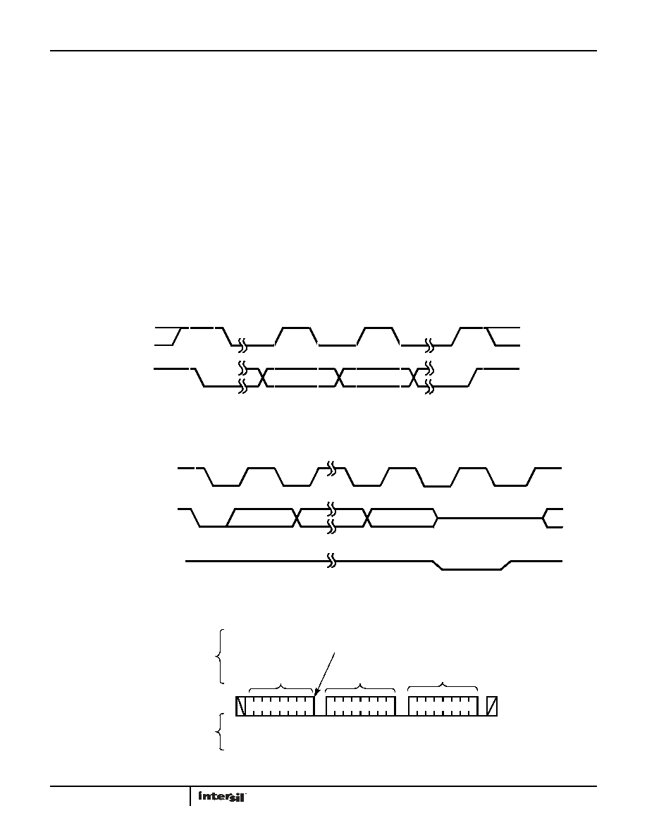
Data states on the SDA line can change only during SCL LOW
periods. SDA state changes during SCL HIGH are reserved for
indicating START and STOP conditions (see Figure 17). On power-
up of the ISL12022M, the SDA pin is in the input mode.
All I2C interface operations must begin with a START condition,
which is a HIGH to LOW transition of SDA while SCL is HIGH. The
ISL12022M continuously monitors the SDA and SCL lines for the
START condition and does not respond to any command until this
condition is met (see Figure 17). A START condition is ignored
during the power-up sequence.
All I2C interface operations must be terminated by a STOP
condition, which is a LOW to HIGH transition of SDA while SCL is
HIGH (see Figure 17). A STOP condition at the end of a read
operation or at the end of a write operation to memory only
places the device in its standby mode.
FIGURE 17. VALID DATA CHANGES, START AND STOP CONDITIONS
FIGURE 18. ACKNOWLEDGE RESPONSE FROM RECEIVER
FIGURE 19. BYTE WRITE SEQUENCE (SLAVE ADDRESS FOR CSR SHOWN)
SDA
SCL
START
DATA
STOP
STABLE
CHANGE
DATA
STABLE
SDA OUTPUT FROM
TRANSMITTER
SDA OUTPUT FROM
RECEIVER
8
1
9
START
ACK
SCL FROM
MASTER
HIGH IMPEDANCE
S
T
A
R
T
S
T
O
P
IDENTIFICATION
BYTE
DATA
BYTE
A
C
K
SIGNALS FROM THE
MASTER
SIGNALS FROM
THE ISL12022M
A
C
K
10
0
11
A
C
K
WRITE
SIGNAL AT SDA
00 00
11 1
ADDRESS
BYTE
相关PDF资料 |
PDF描述 |
|---|---|
| UCY2G470MHD3TN | CAP ALUM 47UF 400V 20% RADIAL |
| RMM11DSXH | CONN EDGECARD 22POS DIP .156 SLD |
| EBM30DRSS | CONN EDGECARD 60POS DIP .156 SLD |
| ECO-S1EA183CA | CAP ALUM 18000UF 25V 20% SNAP |
| RMM11DRXN | CONN EDGECARD 22POS DIP .156 SLD |
相关代理商/技术参数 |
参数描述 |
|---|---|
| ISL12022MIBZR5421 | 功能描述:实时时钟 REAL TIME CLK W/MFK IMPROVED ESD AIR RoHS:否 制造商:Microchip Technology 功能:Clock, Calendar. Alarm RTC 总线接口:I2C 日期格式:DW:DM:M:Y 时间格式:HH:MM:SS RTC 存储容量:64 B 电源电压-最大:5.5 V 电源电压-最小:1.8 V 最大工作温度:+ 85 C 最小工作温度: 安装风格:Through Hole 封装 / 箱体:PDIP-8 封装:Tube |
| ISL12022MIBZ-T | 功能描述:实时时钟 REAL TIME CLK & TEMP COMPENSATED CRYSTAL RoHS:否 制造商:Microchip Technology 功能:Clock, Calendar. Alarm RTC 总线接口:I2C 日期格式:DW:DM:M:Y 时间格式:HH:MM:SS RTC 存储容量:64 B 电源电压-最大:5.5 V 电源电压-最小:1.8 V 最大工作温度:+ 85 C 最小工作温度: 安装风格:Through Hole 封装 / 箱体:PDIP-8 封装:Tube |
| ISL12022MIBZ-T7A | 功能描述:IC RTC/CALENDAR TEMP SNSR 20SOIC RoHS:否 类别:集成电路 (IC) >> 时钟/计时 - 实时时钟 系列:- 产品培训模块:Obsolescence Mitigation Program 标准包装:1 系列:- 类型:时钟/日历 特点:警报器,闰年,SRAM 存储容量:- 时间格式:HH:MM:SS(12/24 小时) 数据格式:YY-MM-DD-dd 接口:SPI 电源电压:2 V ~ 5.5 V 电压 - 电源,电池:- 工作温度:-40°C ~ 85°C 安装类型:表面贴装 封装/外壳:8-WDFN 裸露焊盘 供应商设备封装:8-TDFN EP 包装:管件 |
| ISL12022MIBZ-TR5421 | 功能描述:实时时钟 REAL TIME CLK W/MFK IMPROVED ESD AIR RoHS:否 制造商:Microchip Technology 功能:Clock, Calendar. Alarm RTC 总线接口:I2C 日期格式:DW:DM:M:Y 时间格式:HH:MM:SS RTC 存储容量:64 B 电源电压-最大:5.5 V 电源电压-最小:1.8 V 最大工作温度:+ 85 C 最小工作温度: 安装风格:Through Hole 封装 / 箱体:PDIP-8 封装:Tube |
| ISL12022MR5421 | 制造商:INTERSIL 制造商全称:Intersil Corporation 功能描述:Low Power RTC with Battery Backed SRAM, Integrated 5ppm |
发布紧急采购,3分钟左右您将得到回复。