- 您现在的位置:买卖IC网 > PDF目录16336 > ISL12022MIBZ-EVAL (Intersil)EVAL BOARD FOR ISL12022MIBZ PDF资料下载
参数资料
| 型号: | ISL12022MIBZ-EVAL |
| 厂商: | Intersil |
| 文件页数: | 19/31页 |
| 文件大小: | 0K |
| 描述: | EVAL BOARD FOR ISL12022MIBZ |
| 应用说明: | Addressing Power Issues in Real Time Clock Appls |
| 产品培训模块: | Solutions for Industrial Control Applications |
| 标准包装: | 1 |
| 系列: | * |
第1页第2页第3页第4页第5页第6页第7页第8页第9页第10页第11页第12页第13页第14页第15页第16页第17页第18页当前第19页第20页第21页第22页第23页第24页第25页第26页第27页第28页第29页第30页第31页
ISL12022M
26
FN6668.9
June 20, 2012
Application Section
Power Supply Considerations
The ISL12022M contains programmed EEPROM registers which
are recalled to volatile RAM registers during initial power-up.
These registers contain DC voltage, frequency and temperature
calibration settings. Initial power-up can be either application of
VBAT or VDD power, whichever is first. It is important that the
initial power-up meet the power supply slew rate specification to
avoid faulty EEPROM power-up recall. Also, any glitches or low
voltage DC pauses should be avoided, as these may activate
recall at a low voltage and load erroneous data into the
calibration registers. Note that a very slow VDD ramp rate
(outside data sheet limits) will almost always trigger erroneous
recall and should be avoided entirely.
Battery Backup Details
The ISL12022M has automatic switchover to battery backup
when the VDD drops below the VBAT mode threshold. A wide
variety of backup sources can be used, including standard and
rechargeable lithium, supercapacitors, or regulated secondary
sources. The serial interface is disabled in battery backup, while
the oscillator and RTC registers are operational. The SRAM
register contents are powered to preserve their contents as well.
The input voltage range for VBAT is 1.8V to 5.5V, but keep in mind
the temperature compensation only operates for VBAT >2.7V. Note
that the device is not guaranteed to operate with a VBAT < 1.8V, so
the battery should be changed before discharging to that level. It is
strongly advised to monitor the low battery indicators in the status
registers and take action to replace discharged batteries.
If a supercapacitor is used, it is possible that it may discharge to
below 1.8V during prolonged power-down. Once powered up, the
device may lose serial bus communications until both VDD and
VBAT are powered down together. To avoid that situation, including
situations where a battery may discharge deeply, the circuit in
Figure 22 can be used.
The diode, DBAT will add a small drop to the battery voltage but
will protect the circuit should battery voltage drop below 1.8V.
The jumper is added as a safeguard should the battery ever need
to be disconnected from the circuit.
The VDD negative slew rate should be limited to below the data
sheet spec (10V/ms) otherwise battery switchover can be
delayed, resulting in SRAM contents corruption and oscillator
operation interruption.
Some applications will require separate supplies for the RTC VDD
and the I2C pull-ups. This is not advised, as it may compromise the
operation of the I2C bus. For applications that do require serial bus
communication with the RTC VDD powered down, the SDA pin
must be pulled low during the time the RTC VDD ramps down to 0V.
Otherwise, the device may lose serial bus communications once
VDD is powered up, and will return to normal operation ONLY once
VDD and VBAT are both powered down together.
Layout Considerations
The ISL12022M contains a quartz crystal and requires special
handling during PC board assembly. Excessive shock and vibrations
should be avoided, especially with automated handling equipment.
Ultrasound cleaning is not advisable as it subjects the crystal to
specifications tables, which pertains to solder reflow effects on
oscillator accuracy.
The part of the package from pin 1 to 5 and from pin 16 to 20
contains the crystal. Low frequency RTC crystals are known to pick
up noise very easily if layout precautions are not followed, even
embedded within a plastic package. Most instances of erratic
clocking or large accuracy errors can be traced to the susceptibility
of the oscillator circuit to interference from adjacent high speed
clock or data lines. Careful layout of the RTC circuit will avoid noise
pickup and insure accurate clocking.
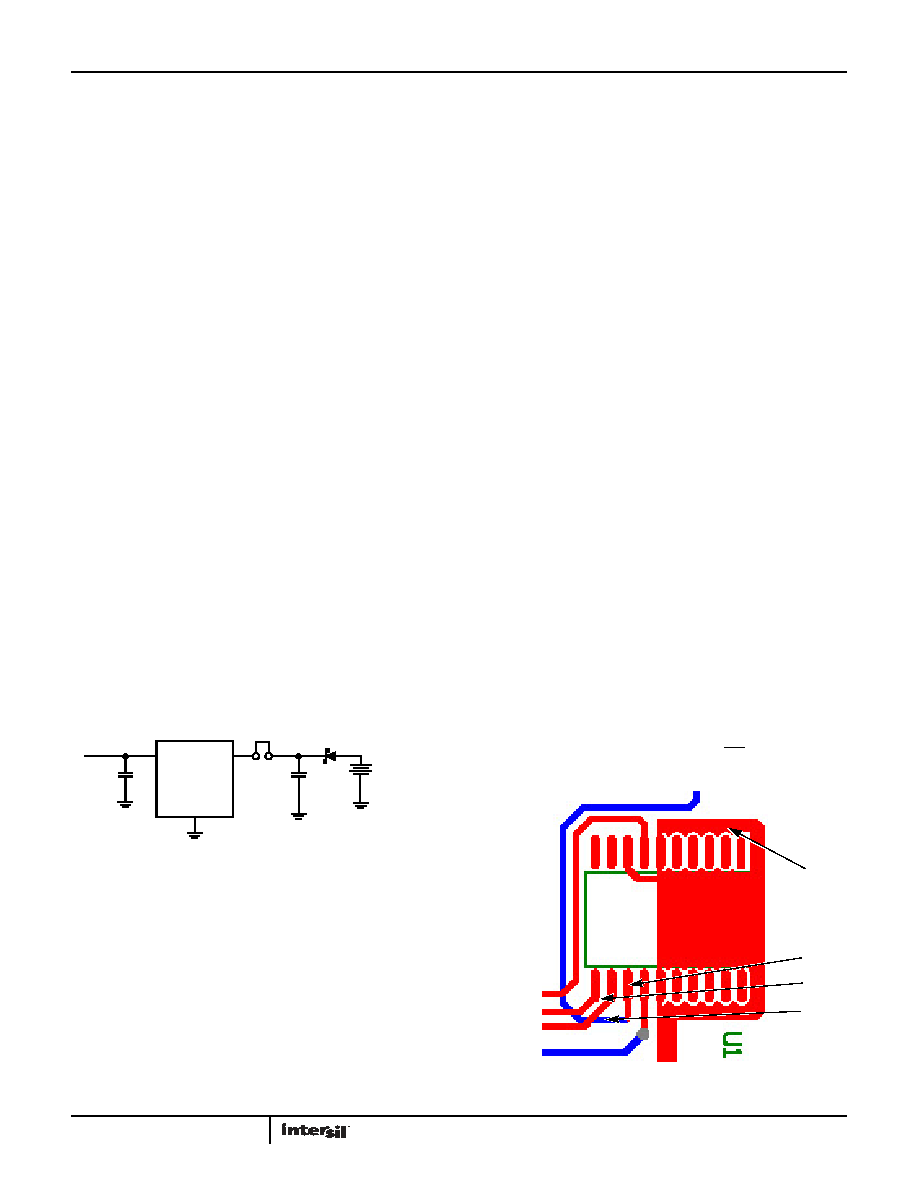
Figure 23 shows a suggested layout for the ISL12022M device.
The following main precautions should be followed:
Do not run the serial bus lines or any high speed logic lines in
the vicinity of pins 1 and 20, or under the package. These logic
level lines can induce noise in the oscillator circuit, causing
misclocking.
Add a ground trace around the device with one end terminated at
the chip ground. This guard ring will provide termination for
emitted noise in the vicinity of the RTC device
Be sure to ground pins 6 and 15 as well as pin 8 as these all
insure the integrity of the device ground
Add a 0.1F decoupling capacitor at the device VDD pin,
especially when using the 32.768kHz FOUT function.
The best way to run clock lines around the RTC is to stay outside of
the ground ring by at least a few millimeters. Also, use the VBAT
and VDD as guard ring lines as well, they can isolate clock lines
from the oscillator section. In addition, if the IRQ/FOUT pin is used
as a clock, it should be routed away from the RTC device as well.
FIGURE 22. SUGGESTED BATTERY BACKUP CIRCUIT
DBAT
CBAT
CIN
BAT43W
0.1F
VDD = 2.7V
VBAT = 1.8V
JBAT
ISL12022M
VDD
GND
VBAT
TO 3.2V
TO 5.5V
+
FIGURE 23. SUGGESTED LAYOUT FOR THE ISL12022M
FOUT
SCL
SDA
GROUND
RING
相关PDF资料 |
PDF描述 |
|---|---|
| UCY2G470MHD3TN | CAP ALUM 47UF 400V 20% RADIAL |
| RMM11DSXH | CONN EDGECARD 22POS DIP .156 SLD |
| EBM30DRSS | CONN EDGECARD 60POS DIP .156 SLD |
| ECO-S1EA183CA | CAP ALUM 18000UF 25V 20% SNAP |
| RMM11DRXN | CONN EDGECARD 22POS DIP .156 SLD |
相关代理商/技术参数 |
参数描述 |
|---|---|
| ISL12022MIBZR5421 | 功能描述:实时时钟 REAL TIME CLK W/MFK IMPROVED ESD AIR RoHS:否 制造商:Microchip Technology 功能:Clock, Calendar. Alarm RTC 总线接口:I2C 日期格式:DW:DM:M:Y 时间格式:HH:MM:SS RTC 存储容量:64 B 电源电压-最大:5.5 V 电源电压-最小:1.8 V 最大工作温度:+ 85 C 最小工作温度: 安装风格:Through Hole 封装 / 箱体:PDIP-8 封装:Tube |
| ISL12022MIBZ-T | 功能描述:实时时钟 REAL TIME CLK & TEMP COMPENSATED CRYSTAL RoHS:否 制造商:Microchip Technology 功能:Clock, Calendar. Alarm RTC 总线接口:I2C 日期格式:DW:DM:M:Y 时间格式:HH:MM:SS RTC 存储容量:64 B 电源电压-最大:5.5 V 电源电压-最小:1.8 V 最大工作温度:+ 85 C 最小工作温度: 安装风格:Through Hole 封装 / 箱体:PDIP-8 封装:Tube |
| ISL12022MIBZ-T7A | 功能描述:IC RTC/CALENDAR TEMP SNSR 20SOIC RoHS:否 类别:集成电路 (IC) >> 时钟/计时 - 实时时钟 系列:- 产品培训模块:Obsolescence Mitigation Program 标准包装:1 系列:- 类型:时钟/日历 特点:警报器,闰年,SRAM 存储容量:- 时间格式:HH:MM:SS(12/24 小时) 数据格式:YY-MM-DD-dd 接口:SPI 电源电压:2 V ~ 5.5 V 电压 - 电源,电池:- 工作温度:-40°C ~ 85°C 安装类型:表面贴装 封装/外壳:8-WDFN 裸露焊盘 供应商设备封装:8-TDFN EP 包装:管件 |
| ISL12022MIBZ-TR5421 | 功能描述:实时时钟 REAL TIME CLK W/MFK IMPROVED ESD AIR RoHS:否 制造商:Microchip Technology 功能:Clock, Calendar. Alarm RTC 总线接口:I2C 日期格式:DW:DM:M:Y 时间格式:HH:MM:SS RTC 存储容量:64 B 电源电压-最大:5.5 V 电源电压-最小:1.8 V 最大工作温度:+ 85 C 最小工作温度: 安装风格:Through Hole 封装 / 箱体:PDIP-8 封装:Tube |
| ISL12022MR5421 | 制造商:INTERSIL 制造商全称:Intersil Corporation 功能描述:Low Power RTC with Battery Backed SRAM, Integrated 5ppm |
发布紧急采购,3分钟左右您将得到回复。