参数资料
| 型号: | ISL6565BCV-T |
| 厂商: | Intersil |
| 文件页数: | 16/28页 |
| 文件大小: | 0K |
| 描述: | IC REG CTRLR BUCK PWM VM 28TSSOP |
| 标准包装: | 2,500 |
| PWM 型: | 电压模式 |
| 输出数: | 1 |
| 频率 - 最大: | 1.5MHz |
| 占空比: | 66.7% |
| 电源电压: | 4.75 V ~ 5.25 V |
| 降压: | 是 |
| 升压: | 无 |
| 回扫: | 无 |
| 反相: | 无 |
| 倍增器: | 无 |
| 除法器: | 无 |
| Cuk: | 无 |
| 隔离: | 无 |
| 工作温度: | 0°C ~ 105°C |
| 封装/外壳: | 28-TSSOP(0.173",4.40mm 宽) |
| 包装: | 带卷 (TR) |
第1页第2页第3页第4页第5页第6页第7页第8页第9页第10页第11页第12页第13页第14页第15页当前第16页第17页第18页第19页第20页第21页第22页第23页第24页第25页第26页第27页第28页
�� �
�
�ISL6565A,� ISL6565B�
�The� ISL6565A,� ISL6565B� checks� the� VID� inputs� six� times�
�every� switching� cycle.� If� the� VID� code� is� found� to� have�
�changed,� the� controller� waits� half� of� a� complete� cycle� before�
�executing� a� 12.5mV� change.� If� during� the� half-cycle� wait�
�created� by� pushing� the� average� sense� current� through� a�
�selectable� external� resistor,� R� TCOMP� .�
�VDIFF�
�period,� the� difference� between� the� DAC� level� and� the� new�
�VID� code� changes� sign,� no� change� is� made.� If� the� VID� code�
�is� more� than� 1� bit� higher� or� lower� than� the� DAC� (not�
�recommended),� the� controller� will� execute� 12.5mV� changes�
�six� times� per� cycle� until� VID� and� DAC� are� equal.� It� is�
�-�
�V� DROOP�
�+�
�R� FB�
�FB�
�I� AVG�
�important� to� carefully� control� the� rate� of� VID� stepping� in� 1-bit�
�increments.�
�In� order� to� ensure� the� smooth� transition� of� output� voltage�
�during� VID� change,� a� VID� step� change� smoothing� network� is�
�required� for� an� ISL6565A,� ISL6565B� based� voltage�
�regulator.� This� network� is� composed� of� a� 1k� ?� internal�
�resistor� between� the� output� of� DAC� and� the� capacitor� C� REF� ,�
�between� the� REF� pin� and� ground.� The� selection� of� C� REF� is�
�based� on� the� time� duration� for� 1� bit� VID� change� and� the�
�allowable� delay� time.�
�I� DROOP�
�TCOMP�
�R� TCOMP�
�I� TCOMP�
�K� TC�
�I� AVG�
�ISL6565A,� ISL6565B�
�Assuming� the� microprocessor� controls� the� VID� change� at� 1�
�bit� every� T� VID� ,� the� relationship� between� C� REF� and� T� VID� is�
�given� by� Equation� 15.�
�C� REF� =� 0.004X� T� VID� (EQ.� 15)�
�As� an� example,� for� a� VID� step� change� rate� of� 5� μ� s� per� bit,� the�
�value� of� C� REF� is� 22nF� based� on� Equation� 15.�
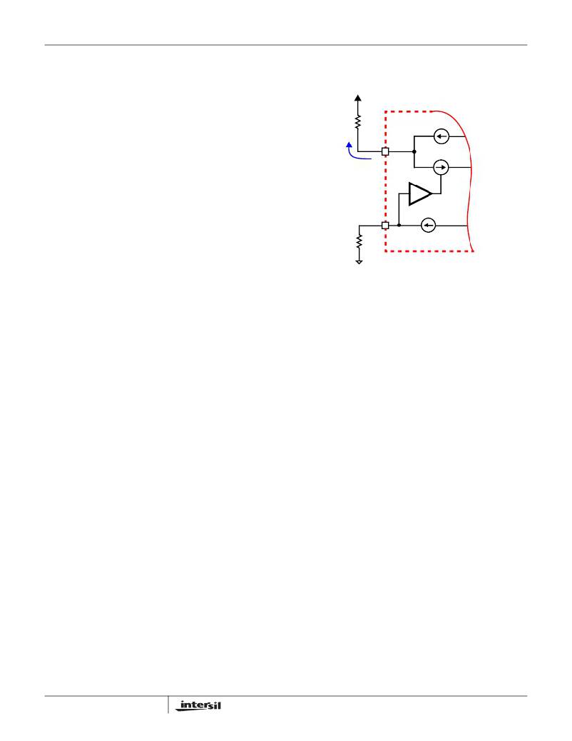
�FIGURE� 10.� TEMPERATURE� COMPENSATION� CIRCUITRY�
�As� shown� in� Figure� 10,� the� voltage� drop� developed� across�
�R� TCOMP� is� then� sensed� and� multiplied� by� a� known� gain,�
�K� TC� ,� which� is� determined� by� the� internal� IC� temperature.�
�This� gain� creates� the� temperature� compensation� current,�
�I� TCOMP� ,� that� is� injected� into� the� FB� pin.�
�Temperature� Compensation�
�I� TCOMP� =� K� TC� ?� (� T� –� 25� )� ?� I� AVG� ?� R� TCOMP�
�(EQ.� 18)�
�MOSFET� r� DS(ON)� and� inductor� DCR� are� both� susceptible� to�
�changes� in� value� due� to� temperature.� Since� output� voltage�
�positioning� is� derived� from� the� channel� current� sensed�
�across� these� two� elements,� any� variation� in� resistance�
�results� in� a� corresponding� error� in� the� output� voltage.�
�The� temperature� coefficient,� α� ,� of� the� r� DS(ON)� or� DCR� is� the�
�parameter� that� determines� how� much� the� resistance� varies�
�with� temperature.� As� temperature� increases� above� ambient,�
�the� average� sensed� current,� I� AVG� ,� changes� in� proportion� to�
�the� temperature� coefficient� and� temperature� rise� as� shown� in�
�Equation� 16.�
�Select� R� TCOMP� such� that� I� TCOMP� equals� I� ERR� over� the�
�entire� range� of� operating� temperature.� The� resulting� droop�
�current� accurately� represents� the� load� current;� achieving� a�
�linear,� temperature-independant� load� line.�
�Initialization�
�Prior� to� initialization,� proper� conditions� must� exist� on� the�
�enable� inputs� and� VCC.� When� the� conditions� are� met,� the�
�controller� begins� soft-start.� Once� the� output� voltage� is� within�
�the� proper� window� of� operation,� the� controller� asserts�
�PGOOD.�
�I� AVG� =� I� AVG� (� T�
�AMBIENT�
�)� ?� [� 1� +� α� (� T� –� T� AMBIENT� )� ]�
�(EQ.� 16)�
�Enable� and� Disable�
�While� in� shutdown� mode,� the� PWM� outputs� are� held� in� a�
�With� this� resulting� error,� I� AVG� can� now� be� described� as� the�
�sum� of� two� parts,� the� average� sensed� current� at� ambient�
�temperature� and� the� resulting� error� current,� I� ERR� ,� due� to� the�
�temperature� rise.�
�high-impedance� state� to� assure� the� drivers� remain� off.� The�
�following� input� conditions� must� be� met� before� the� ISL6565A,�
�ISL6565B� is� released� from� shutdown� mode.�
�1.� The� bias� voltage� applied� at� VCC� must� reach� the� internal�
�power-on� reset� (POR)� rising� threshold.� Once� this�
�I� ERR� (� T� )� =� I� AVG� (� T�
�AMBIENT�
�)� ?� α� ?� (� T� –� T� AMBIENT� )�
�(EQ.� 17)�
�threshold� is� reached,� proper� operation� of� all� aspects� of�
�the� ISL6565A,� ISL6565B� is� guaranteed.� Hysteresis�
�between� the� rising� and� falling� thresholds� assure� that� once�
�In� order� to� compensate� for� this� error� current,� the� ISL6565A,�
�ISL6565B� includes� a� temperature� compensation� circuit� that�
�injects� a� current,� I� TCOMP� ,� into� the� FB� pin.� This� current� is�
�16�
�enabled,� the� ISL6565A,� ISL6565B� will� not� inadvertently�
�turn� off� unless� the� bias� voltage� drops� substantially� (see�
�Electrical� Specifications� ).�
�FN9135.4�
�December� 1,� 2005�
�相关PDF资料 |
PDF描述 |
|---|---|
| ISL6566AIRZ | IC CTRLR PWM 3PHASE BUCK 40-QFN |
| ISL6566CRZ-T | IC CTLR PWM BUCK 3PHASE 40-QFN |
| ISL6567CRZ | IC REG CTRLR BUCK PWM VM 24-QFN |
| ISL6568CRZ-T | IC CTLR PWM BUCK 2PHASE 32-QFN |
| ISL6569ACR-T | IC REG CTRLR BUCK PWM 32-QFN |
相关代理商/技术参数 |
参数描述 |
|---|---|
| ISL6565BCVZ | 功能描述:IC REG CTRLR BUCK PWM VM 28TSSOP RoHS:是 类别:集成电路 (IC) >> PMIC - 稳压器 - DC DC 切换控制器 系列:- 产品培训模块:Lead (SnPb) Finish for COTS Obsolescence Mitigation Program 标准包装:2,500 系列:- PWM 型:电流模式 输出数:1 频率 - 最大:275kHz 占空比:50% 电源电压:18 V ~ 110 V 降压:无 升压:无 回扫:无 反相:无 倍增器:无 除法器:无 Cuk:无 隔离:是 工作温度:-40°C ~ 85°C 封装/外壳:8-SOIC(0.154",3.90mm 宽) 包装:带卷 (TR) |
| ISL6565BCVZ-T | 功能描述:IC REG CTRLR BUCK PWM VM 28TSSOP RoHS:是 类别:集成电路 (IC) >> PMIC - 稳压器 - DC DC 切换控制器 系列:- 产品培训模块:Lead (SnPb) Finish for COTS Obsolescence Mitigation Program 标准包装:2,500 系列:- PWM 型:电流模式 输出数:1 频率 - 最大:275kHz 占空比:50% 电源电压:18 V ~ 110 V 降压:无 升压:无 回扫:无 反相:无 倍增器:无 除法器:无 Cuk:无 隔离:是 工作温度:-40°C ~ 85°C 封装/外壳:8-SOIC(0.154",3.90mm 宽) 包装:带卷 (TR) |
| ISL6566ACRZ | 功能描述:IC CTRLR PWM 3PHASE BUCK 40-QFN RoHS:是 类别:集成电路 (IC) >> PMIC - 稳压器 - 专用型 系列:- 标准包装:43 系列:- 应用:控制器,Intel VR11 输入电压:5 V ~ 12 V 输出数:1 输出电压:0.5 V ~ 1.6 V 工作温度:-40°C ~ 85°C 安装类型:表面贴装 封装/外壳:48-VFQFN 裸露焊盘 供应商设备封装:48-QFN(7x7) 包装:管件 |
| ISL6566ACRZ-T | 功能描述:IC CTRLR PWM 3PHASE BUCK 40-QFN RoHS:是 类别:集成电路 (IC) >> PMIC - 稳压器 - 专用型 系列:- 标准包装:43 系列:- 应用:控制器,Intel VR11 输入电压:5 V ~ 12 V 输出数:1 输出电压:0.5 V ~ 1.6 V 工作温度:-40°C ~ 85°C 安装类型:表面贴装 封装/外壳:48-VFQFN 裸露焊盘 供应商设备封装:48-QFN(7x7) 包装:管件 |
| ISL6566AIRZ | 功能描述:IC CTRLR PWM 3PHASE BUCK 40-QFN RoHS:是 类别:集成电路 (IC) >> PMIC - 稳压器 - 专用型 系列:- 标准包装:43 系列:- 应用:控制器,Intel VR11 输入电压:5 V ~ 12 V 输出数:1 输出电压:0.5 V ~ 1.6 V 工作温度:-40°C ~ 85°C 安装类型:表面贴装 封装/外壳:48-VFQFN 裸露焊盘 供应商设备封装:48-QFN(7x7) 包装:管件 |
发布紧急采购,3分钟左右您将得到回复。