参数资料
| 型号: | ISL6565BCV-T |
| 厂商: | Intersil |
| 文件页数: | 21/28页 |
| 文件大小: | 0K |
| 描述: | IC REG CTRLR BUCK PWM VM 28TSSOP |
| 标准包装: | 2,500 |
| PWM 型: | 电压模式 |
| 输出数: | 1 |
| 频率 - 最大: | 1.5MHz |
| 占空比: | 66.7% |
| 电源电压: | 4.75 V ~ 5.25 V |
| 降压: | 是 |
| 升压: | 无 |
| 回扫: | 无 |
| 反相: | 无 |
| 倍增器: | 无 |
| 除法器: | 无 |
| Cuk: | 无 |
| 隔离: | 无 |
| 工作温度: | 0°C ~ 105°C |
| 封装/外壳: | 28-TSSOP(0.173",4.40mm 宽) |
| 包装: | 带卷 (TR) |
第1页第2页第3页第4页第5页第6页第7页第8页第9页第10页第11页第12页第13页第14页第15页第16页第17页第18页第19页第20页当前第21页第22页第23页第24页第25页第26页第27页第28页
�� �
�
�ISL6565A,� ISL6565B�
�V� IN�
�I�
�L�
�below� to� choose� the� component� values� for� the� resistor�
�divider� R-C� network� for� each� phase.�
�ISL6605�
�L�
�DCR�
�INDUCTOR�
�V� L� (s)�
�V� OUT�
�C� OUT�
�1.� Load� the� regulator� to� full� load� and� allow� the� board� to� heat�
�until� the� output� voltage� stabilizes� (usually� several�
�minutes).�
�2.� Measure� the� current� flowing� through� each� phase,�
�PWM(n)�
�R� 1�
�V� C� (s)�
�C�
�labeling� the� highest� phase� current,� I� HIGH� ,� and� the� other,�
�lower� phase� currents� I� LOW� (1)� and� I� LOW� (2).�
�3.� Individually,� plug� the� values� for� each� low� phase� current,�
�ISL6565B�
�R� 2�
�R� ISEN�
�I� LOW� (n),� the� highest� phase� current,� I� HIGH� ,� the� full� load�
�current,� I� LOAD� ,� and� the� number� of� phases,� N,� into�
�Equation� 30� to� calculate� the� resistor� divider� ratio,� K� LOW� ,�
�for� each� low� phase.� (NOTE:� The� phase� with� the� highest�
�ISEN(n)�
�I� SEN�
�phase� current� is� the� reference� phase� and� it� will� not� use� a�
�resistor� divider� network,� keeping� its� resistor� divider� ratio�
�equal� to� 1.)�
�I� LOW� (� n� )� –� I� HIGH�
�I� LOAD� ?� N�
�ICOMMON�
�K� LOW� (� n� )� =� 1� +� ---------------------------------------------�
�(EQ.� 30)�
�4.� For� each� phase,� calculate� the� values� for� the� new� R-C�
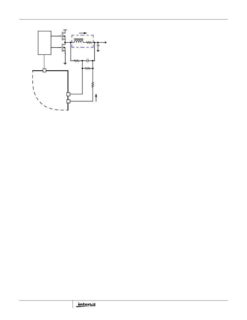
�FIGURE� 16.� DCR� SENSING� CONFIGURATION�
�The� time� constant� of� this� R-C� network� must� match� the� time�
�constant� of� the� inductor� L/DCR.� Follow� the� steps� below� to�
�network� sense� resistors,� R� 1,new� and� R� 2,new� ,� by� plugging�
�in� each� phase’s� new� resistor� divider� ratio,� K� LOW� ,� and�
�each� phase’s� present� sense� resistor� R� 1� ,� into� Equations�
�31� and� 32.�
�R� 1� ,� new� (� n� )� =� -------------------------�
�R� 1� (� n� )�
�R� 2� ,� new� (� n� )� =� -----------------------------------�
�choose� the� component� values� for� this� R-C� network.�
�1.� Choose� an� arbitrary� value� for� C.� The� recommended� value�
�is� 0.01� μ� F.�
�2.� Plug� the� Inductor� L� and� DCR� component� values,� and� the�
�values� for� C� chosen� in� steps� 1,� into� Equation� 28� to�
�R� 1� (� n� )�
�K� LOW� (� n� )�
�1� –� K� LOW� (� n� )�
�(EQ.� 31)�
�(EQ.� 32)�
�R� 1� =� ----------------------�
�calculate� your� value� for� R� 1� .� Do� not� populate� R� 2� .�
�L� (EQ.� 28)�
�DCR� ?� C�
�Due� to� errors� in� the� inductance� or� DCR� it� may� be� necessary�
�to� adjust� the� value� of� R� 1� for� each� phase� to� match� the� time�
�constants� correctly.�
�Once� the� R-C� network� components� have� been� chosen,� use�
�Equation� 29� to� calculate� the� value� of� R� ISEN� .� In� Equation� 29,�
�DCR� is� the� DCR� of� the� output� inductor� at� room� temperature,�
�I� FL� is� the� full� load� operating� current,� and� N� is� the� number� of�
�phases.�
�After� calculating� the� new� resistor� divider� sense� resistors,� the�
�phases� will� be� balanced.� It� may� be� necessary� to� adjust� the�
�R� ISEN� resistor� slightly� to� correct� for� any� changes� in� the�
�desired� I� SEN� current� that� results� from� adding� the� resistor�
�dividers.�
�The� phase� currents� might� also� have� to� be� adjusted� if� the�
�components� of� one� or� more� phases� are� inhibited� from�
�effectively� dissipating� their� heat� so� that� the� affected� phases�
�run� hotter� than� desired.� In� this� case� it� may� be� necessary� to�
�adjust� the� resistor� divider� ratio� of� one� or� more� of� the� R-C�
�networks.� Doing� so� adjusts� the� current� through� affected�
�phases� and� can� balance� the� temperatures� of� each� phase.�
�DCR� ?� I� FL�
�–� 6�
�R� ISEN� =� ----------------------------------�
�70� � 10� ?� N�
�(EQ.� 29)�
�Choose� R� 1,new� and� R� 2,new� in� relation� to� the� desired� change�
�in� temperature,� as� described� in� Equations� 33� and� 34,� in� order�
�to� cause� less� current� to� flow� in� the� hotter� phase.�
�R� 1� ,� new� =� R� 1� ----------� 2�
�R� 1� ?� R� 2�
�R� 2� ,� new� =� ---------------------------------------------------�
�1� –� ---------� 1� -�
�?� T� 2� ?�
�R� 1� +� R� 2� ?� ?� ?�
�Adjusting� Phase� Currents� (ISL6565B� Only)�
�Layout� issues� in� the� core-power� regulator� may� cause� the�
�currents� in� each� phase� to� be� slightly� unbalanced.� This�
�problem� can� be� resolved� without� any� changes� to� the� layout� or�
�any� significant� cost� increase.� The� solution� requires� populating�
�R� 2� in� certain� phases� (as� shown� in� Figure� 16)� to� create� a�
�resistor� divider� ratio,� K,� for� each� phase.� The� time� constant� of�
�?� T�
�?� T� 1�
�?�
�?� ?� T� ?�
�(EQ.� 33)�
�(EQ.� 34)�
�each� new� resistor� divider� R-C� sense� network� must� match� the�
�time� constant� of� the� old� sense� network.� Follow� the� steps�
�21�
�In� Equations� 33� and� 34,� ?� T� 2� is� the� desired� temperature� rise�
�above� the� ambient� temperature,� and� ?� T� 1� is� the� measured�
�temperature� rise� above� the� ambient� temperature.� It� is�
�FN9135.4�
�December� 1,� 2005�
�相关PDF资料 |
PDF描述 |
|---|---|
| ISL6566AIRZ | IC CTRLR PWM 3PHASE BUCK 40-QFN |
| ISL6566CRZ-T | IC CTLR PWM BUCK 3PHASE 40-QFN |
| ISL6567CRZ | IC REG CTRLR BUCK PWM VM 24-QFN |
| ISL6568CRZ-T | IC CTLR PWM BUCK 2PHASE 32-QFN |
| ISL6569ACR-T | IC REG CTRLR BUCK PWM 32-QFN |
相关代理商/技术参数 |
参数描述 |
|---|---|
| ISL6565BCVZ | 功能描述:IC REG CTRLR BUCK PWM VM 28TSSOP RoHS:是 类别:集成电路 (IC) >> PMIC - 稳压器 - DC DC 切换控制器 系列:- 产品培训模块:Lead (SnPb) Finish for COTS Obsolescence Mitigation Program 标准包装:2,500 系列:- PWM 型:电流模式 输出数:1 频率 - 最大:275kHz 占空比:50% 电源电压:18 V ~ 110 V 降压:无 升压:无 回扫:无 反相:无 倍增器:无 除法器:无 Cuk:无 隔离:是 工作温度:-40°C ~ 85°C 封装/外壳:8-SOIC(0.154",3.90mm 宽) 包装:带卷 (TR) |
| ISL6565BCVZ-T | 功能描述:IC REG CTRLR BUCK PWM VM 28TSSOP RoHS:是 类别:集成电路 (IC) >> PMIC - 稳压器 - DC DC 切换控制器 系列:- 产品培训模块:Lead (SnPb) Finish for COTS Obsolescence Mitigation Program 标准包装:2,500 系列:- PWM 型:电流模式 输出数:1 频率 - 最大:275kHz 占空比:50% 电源电压:18 V ~ 110 V 降压:无 升压:无 回扫:无 反相:无 倍增器:无 除法器:无 Cuk:无 隔离:是 工作温度:-40°C ~ 85°C 封装/外壳:8-SOIC(0.154",3.90mm 宽) 包装:带卷 (TR) |
| ISL6566ACRZ | 功能描述:IC CTRLR PWM 3PHASE BUCK 40-QFN RoHS:是 类别:集成电路 (IC) >> PMIC - 稳压器 - 专用型 系列:- 标准包装:43 系列:- 应用:控制器,Intel VR11 输入电压:5 V ~ 12 V 输出数:1 输出电压:0.5 V ~ 1.6 V 工作温度:-40°C ~ 85°C 安装类型:表面贴装 封装/外壳:48-VFQFN 裸露焊盘 供应商设备封装:48-QFN(7x7) 包装:管件 |
| ISL6566ACRZ-T | 功能描述:IC CTRLR PWM 3PHASE BUCK 40-QFN RoHS:是 类别:集成电路 (IC) >> PMIC - 稳压器 - 专用型 系列:- 标准包装:43 系列:- 应用:控制器,Intel VR11 输入电压:5 V ~ 12 V 输出数:1 输出电压:0.5 V ~ 1.6 V 工作温度:-40°C ~ 85°C 安装类型:表面贴装 封装/外壳:48-VFQFN 裸露焊盘 供应商设备封装:48-QFN(7x7) 包装:管件 |
| ISL6566AIRZ | 功能描述:IC CTRLR PWM 3PHASE BUCK 40-QFN RoHS:是 类别:集成电路 (IC) >> PMIC - 稳压器 - 专用型 系列:- 标准包装:43 系列:- 应用:控制器,Intel VR11 输入电压:5 V ~ 12 V 输出数:1 输出电压:0.5 V ~ 1.6 V 工作温度:-40°C ~ 85°C 安装类型:表面贴装 封装/外壳:48-VFQFN 裸露焊盘 供应商设备封装:48-QFN(7x7) 包装:管件 |
发布紧急采购,3分钟左右您将得到回复。