参数资料
| 型号: | MAX3109ETJ+ |
| 厂商: | Maxim Integrated Products |
| 文件页数: | 13/66页 |
| 文件大小: | 0K |
| 描述: | SEMICONDUCTOR OTHER |
| 标准包装: | 60 |
| 系列: | * |
第1页第2页第3页第4页第5页第6页第7页第8页第9页第10页第11页第12页当前第13页第14页第15页第16页第17页第18页第19页第20页第21页第22页第23页第24页第25页第26页第27页第28页第29页第30页第31页第32页第33页第34页第35页第36页第37页第38页第39页第40页第41页第42页第43页第44页第45页第46页第47页第48页第49页第50页第51页第52页第53页第54页第55页第56页第57页第58页第59页第60页第61页第62页第63页第64页第65页第66页
Dual Serial UART with 128-Word FIFOs
MAX3109
20
Maxim Integrated
The following is an example of how to calculate the divi-
sor. It is based on a required baud rate of 190kbaud
and a reference input frequency of 28.23MHz and 1x
(default) rate mode.
The ideal divisor is calculated as:
D = 28,230,000/(16 x 190,000) = 9.286
hence DIV = 9.
FRACT = ROUND(16 x 0.286) = 5
so DIVMSB = 0x00, DIVLSB = 0x09, and BRGConfig[3:0]
= 0x05.
The resulting actual baud rate can be calculated as:
×
=
×
REF
ACTUAL
f
RateMode
BR
16 D
For this example:
DACTUAL = 9 + 5/16 = 9.3125, RateMode = 1, and
BRACTUAL = 28,230,000/(16 x 9.3125) = 189463 baud.
Thus, the actual baud rate is within 0.28% of the ideal
rate.
2x and 4x Rate Modes
To support higher baud rates than possible with stan-
dard operation using 16x sampling, the MAX3109 offers
2x and 4x rate modes. In these modes, the reference
clock rate only needs to be either 8x or 4x higher than the
baud rate, respectively. In 4x rate mode, each received
bit is only sampled once at the midbit instant instead of
the usual three samples to determine the logic value of
the received bit. This reduces the ability to detect line
noise on the received data in 4x rate mode. The 2x and
4x rate modes are selectable through BRGConfig[5:4].
Note that IrDA encoding and decoding does not operate
in 2x and 4x rate modes.
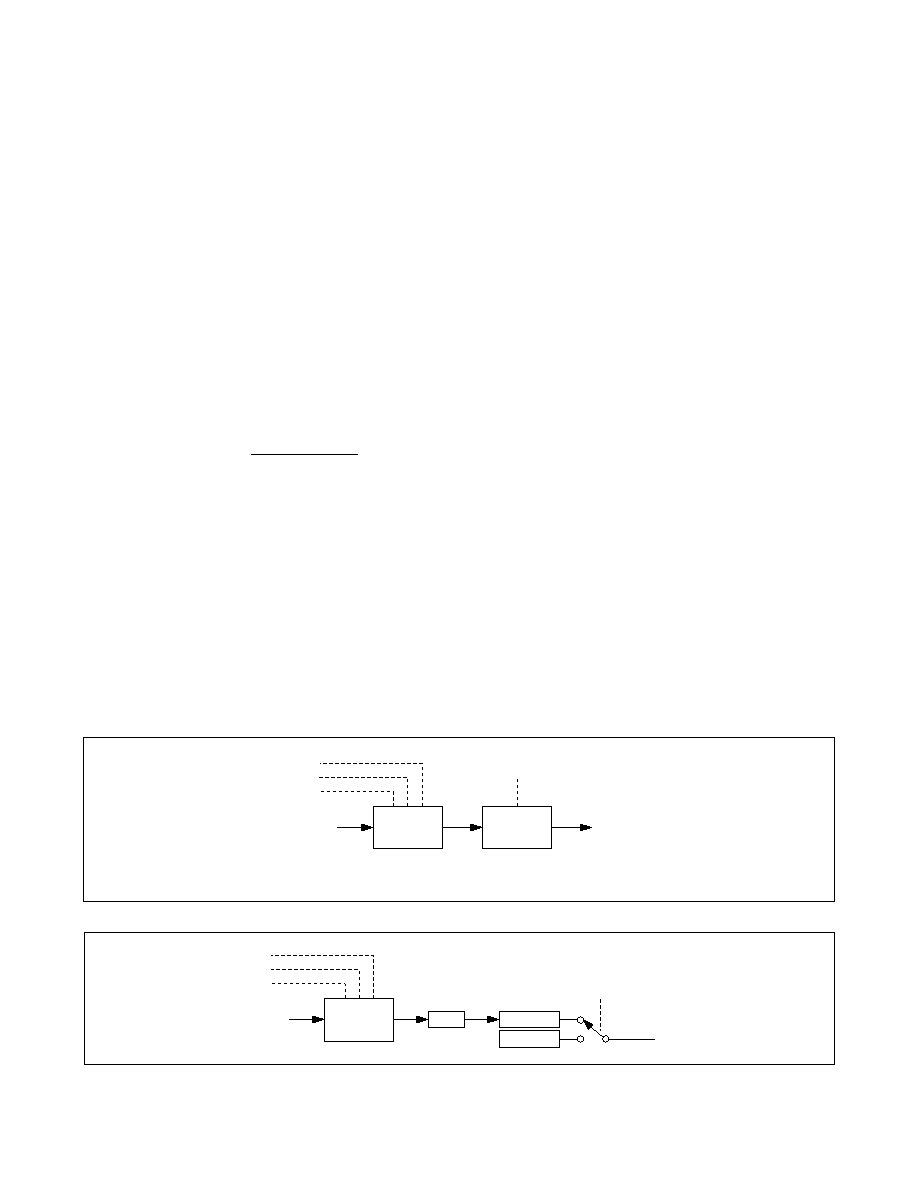
When 2x rate mode is selected, the actual baud rate is
twice the rate programmed into the baud-rate genera-
tor. If 4x rate mode is enabled, the actual baud rate on
the line is quadruple that of the programmed baud rate
(Figure 8).
Low-Frequency Timer
Each UART has a general-purpose timer that can be
used to generate a low-frequency clock at a GPIO
output and can, for example, be used to drive external
LEDs. The low-frequency clock is a divided replica of the
given UART baud-rate clock. The timer for each UART
is internally routed to the respective GPIO_ output when
enabled by the TIMER2 register as follows:
U
UART0: GPIO1
U
UART1: GPIO5
The clock pulses at the GPIOs are generated at a rate
defined by the baud-rate generator and the timer divider
(Figure 9). The baud-rate generator clock frequency is
divided by (1024 x Timer[14:0]) to produce the GPIO_
clock, where Timer[14:0] is the 15-bit value programmed
into the TIMER1 and TIMER2 registers. The timer output
is 50% duty cycle clock.
Figure 8. 2x and 4x Baud Rates
Figure 9. GPIO_ Clock Pulse Generator
FRACTIONAL
RATE
GENERATOR
fREF
BAUD RATE
BRGConfig[5:4]
DIVLSB
DIVMSB
NOTE: IrDA DOES NOT WORK IN 2x AND 4x MODES.
FRACT
1x, 2x, 4x RATE
MODES
FRACTIONAL
RATE
GENERATOR
fREF
÷TIMERx
GPIO_
TmrToGPIO
÷1024
DIVLSB
DIVMSB
FRACT
相关PDF资料 |
PDF描述 |
|---|---|
| MAX310CPE | IC VIDEO MULTIPLEXER 8X1 16DIP |
| MAX3110EENI+G36 | IC UART SPI COMPAT 28-DIP |
| MAX3120CUA+ | IC TXRX INFRARED IRDA 8-UMAX |
| MAX3120EUA | IC TXRX 3V IRDA IR 3V 8-UMAX |
| MAX312ESE | IC SWITCH QUAD SPST 16SOIC |
相关代理商/技术参数 |
参数描述 |
|---|---|
| MAX3109ETJ+ | 功能描述:UART 接口集成电路 Dual Serial UART with 128-Word FIFOs RoHS:否 制造商:Texas Instruments 通道数量:2 数据速率:3 Mbps 电源电压-最大:3.6 V 电源电压-最小:2.7 V 电源电流:20 mA 最大工作温度:+ 85 C 最小工作温度:- 40 C 封装 / 箱体:LQFP-48 封装:Reel |
| MAX3109ETJ+T | 功能描述:UART 接口集成电路 Dual Serial UART with 128-Word FIFOs RoHS:否 制造商:Texas Instruments 通道数量:2 数据速率:3 Mbps 电源电压-最大:3.6 V 电源电压-最小:2.7 V 电源电流:20 mA 最大工作温度:+ 85 C 最小工作温度:- 40 C 封装 / 箱体:LQFP-48 封装:Reel |
| MAX310C/D | 功能描述:多路器开关 IC RoHS:否 制造商:Texas Instruments 通道数量:1 开关数量:4 开启电阻(最大值):7 Ohms 开启时间(最大值): 关闭时间(最大值): 传播延迟时间:0.25 ns 工作电源电压:2.3 V to 3.6 V 工作电源电流: 最大工作温度:+ 85 C 安装风格:SMD/SMT 封装 / 箱体:UQFN-16 |
| MAX310CPE | 功能描述:多路器开关 IC RoHS:否 制造商:Texas Instruments 通道数量:1 开关数量:4 开启电阻(最大值):7 Ohms 开启时间(最大值): 关闭时间(最大值): 传播延迟时间:0.25 ns 工作电源电压:2.3 V to 3.6 V 工作电源电流: 最大工作温度:+ 85 C 安装风格:SMD/SMT 封装 / 箱体:UQFN-16 |
| MAX310CPE+ | 功能描述:多路器开关 IC 8:1 Unbuffered RF Video MUX RoHS:否 制造商:Texas Instruments 通道数量:1 开关数量:4 开启电阻(最大值):7 Ohms 开启时间(最大值): 关闭时间(最大值): 传播延迟时间:0.25 ns 工作电源电压:2.3 V to 3.6 V 工作电源电流: 最大工作温度:+ 85 C 安装风格:SMD/SMT 封装 / 箱体:UQFN-16 |
发布紧急采购,3分钟左右您将得到回复。