参数资料
| 型号: | MAX3109ETJ+ |
| 厂商: | Maxim Integrated Products |
| 文件页数: | 9/66页 |
| 文件大小: | 0K |
| 描述: | SEMICONDUCTOR OTHER |
| 标准包装: | 60 |
| 系列: | * |
第1页第2页第3页第4页第5页第6页第7页第8页当前第9页第10页第11页第12页第13页第14页第15页第16页第17页第18页第19页第20页第21页第22页第23页第24页第25页第26页第27页第28页第29页第30页第31页第32页第33页第34页第35页第36页第37页第38页第39页第40页第41页第42页第43页第44页第45页第46页第47页第48页第49页第50页第51页第52页第53页第54页第55页第56页第57页第58页第59页第60页第61页第62页第63页第64页第65页第66页
Dual Serial UART with 128-Word FIFOs
MAX3109
17
Maxim Integrated
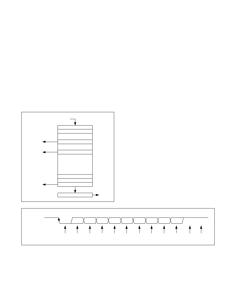
Figure 3. Transmit FIFO Signals
The contents of the TxFIFO and RxFIFO are both cleared
when the MODE2[1]: FIFORst bit is set high
.
Transmitter Operation
Figure 3 shows the structure of the transmitter with the
TxFIFO. The transmit FIFO can hold up to 128 words of
data that are added by writing to the THR register.
The current number of words in the TxFIFO can be read
out by the host controller through the TxFIFOLvl regis-
ter. The transmit FIFO fill level can be programmed to
generate an interrupt when greater than or equal to a
programmed number of words are present in the TxFIFO
through the FIFOTrgLvl register. This TxFIFO interrupt
trigger level is selectable by the FIFOTrgLvl[3:0] bits.
When the transmit FIFO fill level increases to at least the
programmed trigger level, an interrupt is generated in
ISR[4]: TxTrigInt.
An interrupt is generated in ISR[5]: TFifoEmptyInt when
the transmit FIFO is empty. ISR[5] goes high when
the transmitter starts transmitting the last word in the
TxFIFO. An additional interrupt is generated in STSInt[7]:
TxEmptyInt when the transmitter completes transmitting
the last word.
To halt transmission, set the MODE1[1]: TxDisabl bit
high. After TxDisabl is set, the transmitter completes the
transmission of the current character and then ceases
transmission. Turn the transmitter off prior to enabling
auto software flow control and AutoRTS flow control.
The TX_ output logic can be inverted through the
IrDA[5]: TxInv bit. Unless otherwise noted, all transmitter
logic described in this data sheet assumes that TxInv is
set low.
Receiver Operation
The receiver expects the format of the data at RX_ to
be as shown in Figure 4. The quiescent logic state is
logic-high and the first bit (the START bit) is logic-low
(RxInv = 0). The 8-bit data word expected to be received
LSB first. The receiver samples the data near the midbit
instant (Figure 4). The received words and their associ-
ated errors are deposited into the receive FIFO. Errors
and status information are stored for every received word
(Figure 5). The host reads the data out of the receive
FIFO by reading RHR, which comes out oldest data first.
After a word is read out of RHR, LSR contains the status
information for that word.
Figure 4. Receive Data Format
CURRENT FILL LEVEL
TRANSMITTER
TX_
TRANSMIT FIFO
FIFOTrgLvl[3:0]
TRIGGER
ISR[4]
THR
DATA FROM SPI/I2C INTERFACE
128
3
2
1
LEVEL
TxFIFOLvl
EMPTY
ISR[5]
RECEIVED DATA
NOTE: RxInv = 0.
LSB
START
D0
D1
D2
D3
D4
D5
D6
D7
PARITY
STOP
MSB
MIDDATA
SAMPLING
相关PDF资料 |
PDF描述 |
|---|---|
| MAX310CPE | IC VIDEO MULTIPLEXER 8X1 16DIP |
| MAX3110EENI+G36 | IC UART SPI COMPAT 28-DIP |
| MAX3120CUA+ | IC TXRX INFRARED IRDA 8-UMAX |
| MAX3120EUA | IC TXRX 3V IRDA IR 3V 8-UMAX |
| MAX312ESE | IC SWITCH QUAD SPST 16SOIC |
相关代理商/技术参数 |
参数描述 |
|---|---|
| MAX3109ETJ+ | 功能描述:UART 接口集成电路 Dual Serial UART with 128-Word FIFOs RoHS:否 制造商:Texas Instruments 通道数量:2 数据速率:3 Mbps 电源电压-最大:3.6 V 电源电压-最小:2.7 V 电源电流:20 mA 最大工作温度:+ 85 C 最小工作温度:- 40 C 封装 / 箱体:LQFP-48 封装:Reel |
| MAX3109ETJ+T | 功能描述:UART 接口集成电路 Dual Serial UART with 128-Word FIFOs RoHS:否 制造商:Texas Instruments 通道数量:2 数据速率:3 Mbps 电源电压-最大:3.6 V 电源电压-最小:2.7 V 电源电流:20 mA 最大工作温度:+ 85 C 最小工作温度:- 40 C 封装 / 箱体:LQFP-48 封装:Reel |
| MAX310C/D | 功能描述:多路器开关 IC RoHS:否 制造商:Texas Instruments 通道数量:1 开关数量:4 开启电阻(最大值):7 Ohms 开启时间(最大值): 关闭时间(最大值): 传播延迟时间:0.25 ns 工作电源电压:2.3 V to 3.6 V 工作电源电流: 最大工作温度:+ 85 C 安装风格:SMD/SMT 封装 / 箱体:UQFN-16 |
| MAX310CPE | 功能描述:多路器开关 IC RoHS:否 制造商:Texas Instruments 通道数量:1 开关数量:4 开启电阻(最大值):7 Ohms 开启时间(最大值): 关闭时间(最大值): 传播延迟时间:0.25 ns 工作电源电压:2.3 V to 3.6 V 工作电源电流: 最大工作温度:+ 85 C 安装风格:SMD/SMT 封装 / 箱体:UQFN-16 |
| MAX310CPE+ | 功能描述:多路器开关 IC 8:1 Unbuffered RF Video MUX RoHS:否 制造商:Texas Instruments 通道数量:1 开关数量:4 开启电阻(最大值):7 Ohms 开启时间(最大值): 关闭时间(最大值): 传播延迟时间:0.25 ns 工作电源电压:2.3 V to 3.6 V 工作电源电流: 最大工作温度:+ 85 C 安装风格:SMD/SMT 封装 / 箱体:UQFN-16 |
发布紧急采购,3分钟左右您将得到回复。