- 您现在的位置:买卖IC网 > PDF目录2090 > MAX97003EWP+T (Maxim Integrated Products)IC AUDIO SUBSYSTEM LN 20WLP PDF资料下载
参数资料
| 型号: | MAX97003EWP+T |
| 厂商: | Maxim Integrated Products |
| 文件页数: | 39/48页 |
| 文件大小: | 0K |
| 描述: | IC AUDIO SUBSYSTEM LN 20WLP |
| 标准包装: | 2,500 |
| 类型: | D 类;H 类 |
| 输出类型: | 1-通道(单声道)或 2-通道(立体声) |
| 在某负载时最大输出功率 x 通道数量: | 1W x 2 @ 8 欧姆 |
| 电源电压: | 2.7 V ~ 5.5 V |
| 特点: | 消除爆音,差分输入,关闭 |
| 安装类型: | * |
| 供应商设备封装: | * |
| 封装/外壳: | * |
| 包装: | * |
第1页第2页第3页第4页第5页第6页第7页第8页第9页第10页第11页第12页第13页第14页第15页第16页第17页第18页第19页第20页第21页第22页第23页第24页第25页第26页第27页第28页第29页第30页第31页第32页第33页第34页第35页第36页第37页第38页当前第39页第40页第41页第42页第43页第44页第45页第46页第47页第48页
Maxim Integrated Products 44
MAX97003
High-Efficiency, Low-Noise Audio Subsystem
Applications Information
Filterless Class D Operation
Traditional Class D amplifiers require an output filter
to recover the audio signal from the amplifier’s output.
The filters add cost, increase the solution size of the
amplifier, and can decrease efficiency and THD+N
performance. The traditional PWM scheme uses large
differential output swings (2 x VPVDD peak-to-peak) and
causes large ripple currents. Any parasitic resistance in
the filter components results in a loss of power, lowering
the efficiency.
The IC does not require an output filter. The device relies
on the inherent inductance of the speaker coil and the
natural filtering of both the speaker and the human ear
to recover the audio component of the square-wave out-
put. Eliminating the output filter results in a smaller, less
costly, more efficient solution.
Because the frequency of the IC output is well beyond
the bandwidth of most speakers, voice coil movement
due to the square-wave frequency is very small. Although
this movement is small, a speaker not designed to handle
the additional power can be damaged. For optimum
results, use a speaker with a series inductance > 10FH.
Typical 8I speakers exhibit series inductances in the
20FH to 100FH range.
RF Susceptibility
GSM radios transmit using time-division multiple access
(TDMA) with 217Hz intervals. The result is an RF signal
with strong amplitude modulation at 217Hz and its har-
monics that is easily demodulated by audio amplifiers.
The IC is designed specifically to reject RF signals. PCB
layout, however, has a large impact on the susceptibility
of the end product.
In RF applications, improvements to both layout and
component selection decreases the IC’s susceptibility to
RF noise and prevent RF signals from being demodulated
into audible noise. Trace lengths should be kept below
1/4 of the wavelength of the RF frequency of interest.
Minimizing the trace lengths prevents them from function-
ing as antennas and coupling RF signals into the IC. The
wavelength (
l) in meters is given by: l = c/f where c = 3
x 108 m/s, and f = the RF frequency of interest.
Route audio signals on middle layers of the PCB to allow
ground planes above and below to shield them from RF
interference. Ideally, the top and bottom layers of the
PCB should primarily be ground planes to create effec-
tive shielding.
Additional RF immunity can also be obtained by rely-
ing on the self-resonant frequency of capacitors as it
exhibits the frequency response similar to a notch filter.
Depending on the manufacturer, 10pF to 20pF capaci-
tors typically exhibit self resonance at RF frequencies.
These capacitors when placed at the input pins can
effectively shunt the RF noise at the inputs of the IC. For
these capacitors to be effective, they must have a low-
impedance, low-inductance path to the ground plane.
Avoid using microvias to connect to the ground plane
whenever possible as these vias do not conduct well at
RF frequencies.
Startup/Shutdown Sequencing
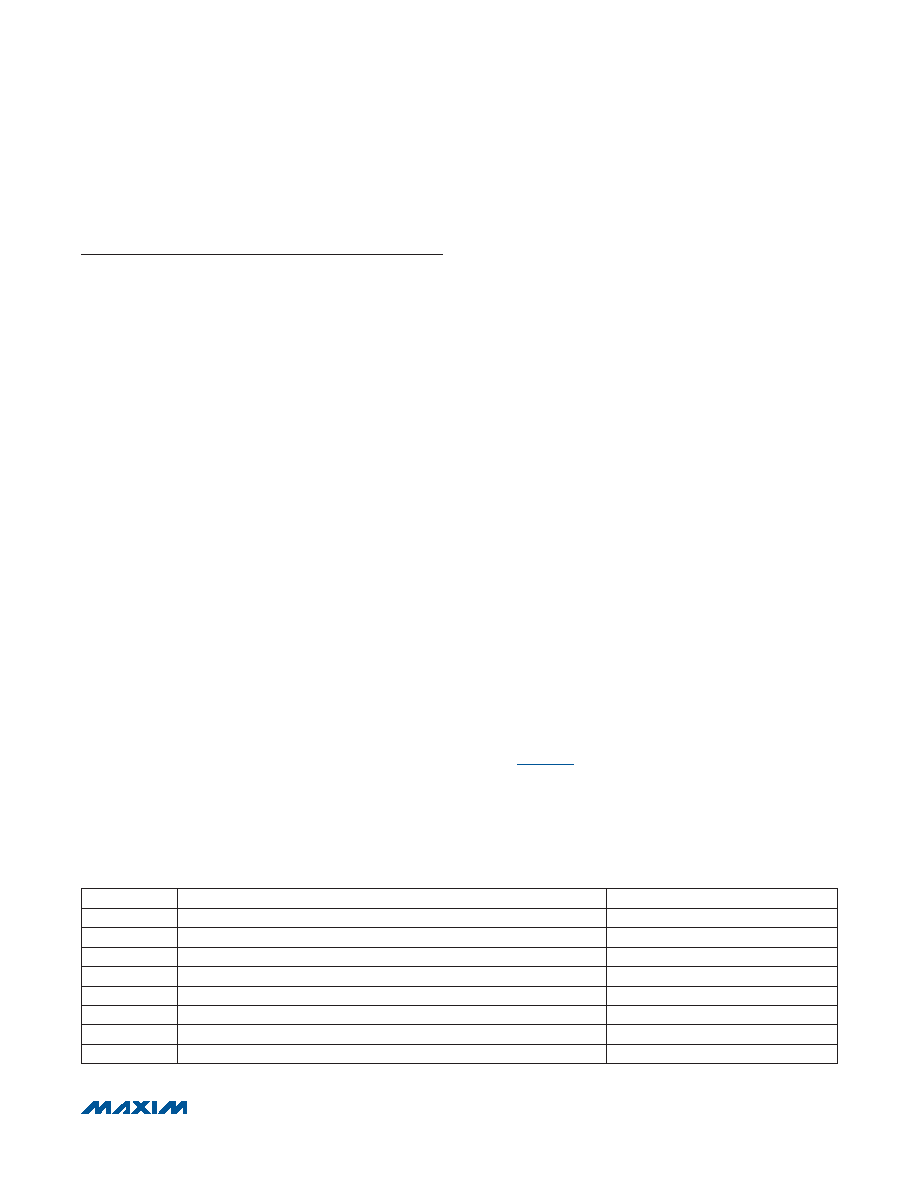
To ensure proper device initialization and minimal click-
and-pop, program the IC’s control registers in the correct
order. Table 13 lists the correct startup sequence for the
device. To shutdown the IC, simply set SHDN = 0.
Table 13. Startup Sequence
SEQUENCE
DESCRIPTION
REGISTERS
1
Ensure SHDN = 0
0x12
2
Configure inputs
0x03, 0x04
3
Configure mixers
0x05, 0x06
4
Configure volume
0x07, 0x08, 0x09
5
Configure output gain
0x10
6
Enable amplifiers
0x12
7
Configure expander and DRC
0x0A–0x0F
10
Set SHDN = 1
0x12
相关PDF资料 |
PDF描述 |
|---|---|
| MAX9700AEUB+ | IC AMP AUDIO 1.6W MONO D 10MSOP |
| MAX9701ETG+T | IC AMP AUDIO PWR 2.2W D 24TQFN |
| MAX9702ETI+T | IC AMP AUDIO PWR 1.8W D 28TQFN |
| MAX9704ETJ+ | IC AMP AUDIO PWR 16W STER 32TQFN |
| MAX9705DEBC+T | IC AMP AUDIO PWR 2.3W D 12UCSP |
相关代理商/技术参数 |
参数描述 |
|---|---|
| MAX9700AEBC | 制造商:Maxim Integrated Products 功能描述:1.2W LOW EMI FILTERLESS CLASS D - Rail/Tube |
| MAX9700AEBC+ | 制造商:Maxim Integrated Products 功能描述:AUD AMP SPKR 1CH MONO 1.6W CLS-D 12UCSP - Rail/Tube |
| MAX9700AEBC+T | 功能描述:音频放大器 1.2W L-EMI Filterles Class D Audio Amp RoHS:否 制造商:STMicroelectronics 产品:General Purpose Audio Amplifiers 输出类型:Digital 输出功率: THD + 噪声: 工作电源电压:3.3 V 电源电流: 最大功率耗散: 最大工作温度: 安装风格:SMD/SMT 封装 / 箱体:TQFP-64 封装:Reel |
| MAX9700AEBC-T | 功能描述:音频放大器 RoHS:否 制造商:STMicroelectronics 产品:General Purpose Audio Amplifiers 输出类型:Digital 输出功率: THD + 噪声: 工作电源电压:3.3 V 电源电流: 最大功率耗散: 最大工作温度: 安装风格:SMD/SMT 封装 / 箱体:TQFP-64 封装:Reel |
| MAX9700AETB | 制造商:Maxim Integrated Products 功能描述:1.2W, LOW EMI, FILTERLESS, CLASS D AUDIO AMPL - Rail/Tube |
发布紧急采购,3分钟左右您将得到回复。