- 您现在的位置:买卖IC网 > PDF目录2090 > MAX97003EWP+T (Maxim Integrated Products)IC AUDIO SUBSYSTEM LN 20WLP PDF资料下载
参数资料
| 型号: | MAX97003EWP+T |
| 厂商: | Maxim Integrated Products |
| 文件页数: | 40/48页 |
| 文件大小: | 0K |
| 描述: | IC AUDIO SUBSYSTEM LN 20WLP |
| 标准包装: | 2,500 |
| 类型: | D 类;H 类 |
| 输出类型: | 1-通道(单声道)或 2-通道(立体声) |
| 在某负载时最大输出功率 x 通道数量: | 1W x 2 @ 8 欧姆 |
| 电源电压: | 2.7 V ~ 5.5 V |
| 特点: | 消除爆音,差分输入,关闭 |
| 安装类型: | * |
| 供应商设备封装: | * |
| 封装/外壳: | * |
| 包装: | * |
第1页第2页第3页第4页第5页第6页第7页第8页第9页第10页第11页第12页第13页第14页第15页第16页第17页第18页第19页第20页第21页第22页第23页第24页第25页第26页第27页第28页第29页第30页第31页第32页第33页第34页第35页第36页第37页第38页第39页当前第40页第41页第42页第43页第44页第45页第46页第47页第48页
Maxim Integrated Products 45
MAX97003
High-Efficiency, Low-Noise Audio Subsystem
Component Selection
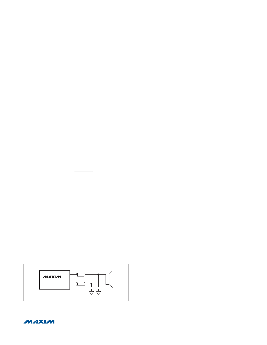
Optional Ferrite Bead Filter
For applications in which speaker leads exceed 20mm,
additional EMI suppression can be achieved by using a
filter constructed from a ferrite bead and a capacitor to
ground (Figure 22). Use a ferrite bead with low DC resis-
tance, high frequency (> 600MHz) impedance between
100I and 600I, and rated for at least 1A. The capacitor
value varies based on the ferrite bead chosen and the
actual speaker lead length. Select a capacitor less than
1nF based on EMI performance.
Input Capacitor
An input capacitor, CIN, in conjunction with the input
impedance of the IC line inputs forms a highpass filter
that removes the DC bias from an incoming analog
signal. The AC-coupling capacitor allows the amplifier
to automatically bias the signal to an optimum DC level.
Assuming zero source impedance, the -3dB point of the
highpass filter is given by:
-3dB
IN IN
1
f
2R C
=
π
under the Input Resistance section. Choose CIN so that
f-3dB is well below the lowest frequency of interest. For
best audio quality, use capacitors whose dielectrics have
low-voltage coefficients, such as tantalum or aluminum
electrolytic. Capacitors with high-voltage coefficients,
such as ceramics, can result in increased distortion at
low frequencies.
Charge-Pump Capacitor Selection
Use capacitors with an ESR less than 100mI for optimum
performance. Low-ESR ceramic capacitors minimize the
output resistance of the charge pump. Most surface-
mount ceramic capacitors satisfy the ESR requirement.
For best performance over the extended temperature
range, select capacitors with an X7R dielectric.
Charge-Pump Flying Capacitor
The value of the flying capacitor (connected between
C1N and C1P) affects the output resistance of the charge
pump. A value that is too small degrades the device’s
ability to provide sufficient current drive, which leads to a
loss of output voltage. Increasing the value of the flying
capacitor reduces the charge-pump output resistance to
an extent. Above 1FF, the on-resistance of the internal
switches and the ESR of external charge-pump capaci-
tors dominate.
Charge-Pump Holding Capacitor
The holding capacitor (bypassing CPVSS) value and ESR
directly affect the ripple at CPVSS. Increasing the capac-
itor’s value reduces output ripple. Likewise, decreasing
the ESR reduces both ripple and output resistance.
Lower capacitance values can be used in systems with
low maximum output power levels. See the Output Power
vs. Load Resistance graph in the Typical Operating
Characteristics section for more information.
Supply Bypassing, Layout, and Grounding
Proper layout and grounding are essential for optimum
performance. Use a large continuous ground plane on
a dedicated layer of the PCB to minimize loop areas.
Connect GND and PGND directly to the ground plane
using the shortest trace length possible. Proper ground-
ing improves audio performance, minimizes crosstalk
between channels, and prevents digital noise from cou-
pling into the analog signals.
Place the capacitor between C1P and C1N as close as
possible to the IC to minimize trace length from C1P
to C1N. Inductance and resistance added to C1P and
C1N reduce the output power of the headphone ampli-
fier. Bypass CPVDD and CPVSS with capacitors located
close to the pins with a short trace length to PGND. Close
decoupling of CPVDD and CPVSS minimizes supply
ripple and maximizes output power from the headphone
amplifier.
Bypass PVDD to PGND with as little trace length as pos-
sible. Connect SPKP and SPKN to the speaker using
the shortest and widest traces possible. Reducing trace
length minimizes radiated EMI. Route SPKP/SPKN as a
differential pair on the PCB to minimize the loop area
and thereby the inductance of the circuit. If filter compo-
nents are used on the speaker outputs, be sure to locate
them as close as possible to the IC to ensure maximum
effectiveness. Minimize the trace length from any ground
tied passive components to PGND to further minimize
radiated EMI.
Figure 22. Optional Class D Ferrite Bead Filter
MAX97000
CLASS D
SPKP
SPKN
相关PDF资料 |
PDF描述 |
|---|---|
| MAX9700AEUB+ | IC AMP AUDIO 1.6W MONO D 10MSOP |
| MAX9701ETG+T | IC AMP AUDIO PWR 2.2W D 24TQFN |
| MAX9702ETI+T | IC AMP AUDIO PWR 1.8W D 28TQFN |
| MAX9704ETJ+ | IC AMP AUDIO PWR 16W STER 32TQFN |
| MAX9705DEBC+T | IC AMP AUDIO PWR 2.3W D 12UCSP |
相关代理商/技术参数 |
参数描述 |
|---|---|
| MAX9700AEBC | 制造商:Maxim Integrated Products 功能描述:1.2W LOW EMI FILTERLESS CLASS D - Rail/Tube |
| MAX9700AEBC+ | 制造商:Maxim Integrated Products 功能描述:AUD AMP SPKR 1CH MONO 1.6W CLS-D 12UCSP - Rail/Tube |
| MAX9700AEBC+T | 功能描述:音频放大器 1.2W L-EMI Filterles Class D Audio Amp RoHS:否 制造商:STMicroelectronics 产品:General Purpose Audio Amplifiers 输出类型:Digital 输出功率: THD + 噪声: 工作电源电压:3.3 V 电源电流: 最大功率耗散: 最大工作温度: 安装风格:SMD/SMT 封装 / 箱体:TQFP-64 封装:Reel |
| MAX9700AEBC-T | 功能描述:音频放大器 RoHS:否 制造商:STMicroelectronics 产品:General Purpose Audio Amplifiers 输出类型:Digital 输出功率: THD + 噪声: 工作电源电压:3.3 V 电源电流: 最大功率耗散: 最大工作温度: 安装风格:SMD/SMT 封装 / 箱体:TQFP-64 封装:Reel |
| MAX9700AETB | 制造商:Maxim Integrated Products 功能描述:1.2W, LOW EMI, FILTERLESS, CLASS D AUDIO AMPL - Rail/Tube |
发布紧急采购,3分钟左右您将得到回复。