- 您现在的位置:买卖IC网 > PDF目录69032 > MCF54418CMJ250 (FREESCALE SEMICONDUCTOR INC) MICROPROCESSOR, PBGA256 PDF资料下载
参数资料
| 型号: | MCF54418CMJ250 |
| 厂商: | FREESCALE SEMICONDUCTOR INC |
| 元件分类: | 微控制器/微处理器 |
| 英文描述: | MICROPROCESSOR, PBGA256 |
| 封装: | 12 X 12 MM, ROHS COMPLAINT, MAPBGA-256 |
| 文件页数: | 19/60页 |
| 文件大小: | 1107K |
| 代理商: | MCF54418CMJ250 |
第1页第2页第3页第4页第5页第6页第7页第8页第9页第10页第11页第12页第13页第14页第15页第16页第17页第18页当前第19页第20页第21页第22页第23页第24页第25页第26页第27页第28页第29页第30页第31页第32页第33页第34页第35页第36页第37页第38页第39页第40页第41页第42页第43页第44页第45页第46页第47页第48页第49页第50页第51页第52页第53页第54页第55页第56页第57页第58页第59页第60页
MCF5441x ColdFire Microprocessor Data Sheet, Rev. 6
Preliminary—Subject to Change Without Notice
Electrical characteristics
Freescale Semiconductor
26
4.8
Oscillator and PLL electrical characteristics
Reference Figure 9 for crystal circuits.
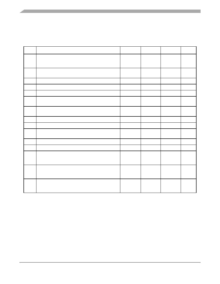
Table 14. PLL electrical characteristics
Num
Characteristic
Symbol
Min
Max
Unit
1
PLL Reference Frequency Range1
Crystal reference
External reference
fref_crystal
fref_ext
141
501
501
1
These reference value ranges are for after a PLL predivider (PREDIV), which can be programmed to 1, 2, 4, 8, or 16.
The PREDIV value can be set while booting from serial flash. In parallel reset configuration, the PREDIV value is set to
one. In this mode, if the input frequency results in an out of range reference frequency, boot the processor in limp
mode, set the proper PREDIV and multiplier settings, and switch to PLL mode.
MHz
2
Core frequency
FB_CLK frequency2 (MISCCR2[FBHALF] = 0)
2
All internal registers retain data at 0 Hz.
fsys
fsys/2
120
60
250
100
MHz
3
VCO frequency
fvco
240
500
MHz
4
DCC frequency3
3 Required only for DDR2 memory.
fDCC
300
500
MHz
5
Crystal start-up time4, 5
4
This parameter is guaranteed by characterization before qualification rather than 100% tested.
5
Proper PC board layout procedures must be followed to achieve specifications.
tcst
—10
ms
6
EXTAL input high voltage
External and limp modes
VIHEXT
EVIH
EVDD
V
7
EXTAL input low voltage
External and limp modes
VILEXT
0EVIL
V
8PLL lock time 4, 6
6
This specification is the PLL lock time only and does not include oscillator start-up time.
tlpll
—50
ms
9
Duty cycle of reference 4
tdc
–45%
+45%
%
10
Crystal capacitive load
CL
—
From crystal
spec
pF
11
Feedback resistor
RF
10
—
M
12
Series resistor
RS
0
200
13
Discrete load capacitance for XTAL
CL_XTAL
—2
C
L –
CS_XTAL –
CPCB_XTAL
7
CPCB_EXTAL and CPCB_XTAL are the measured PCB stray capacitances on EXTAL and XTAL, respectively.
pF
14
Discrete load capacitance for EXTAL
CL_EXTAL
—2
C
L –
CS_EXTAL –
CPCB_EXTAL
pF
15
Peak-to-peak jitter (clock edge to clock edge)
Long term jitter
8
Jitter is the average deviation from the programmed frequency measured over the specified interval at maximum fsys.
Measurements are made with the device powered by filtered supplies and clocked by a stable external clock signal.
Noise injected into the PLL circuitry via PLL VDD, EVDD, and VSS and variation in crystal oscillator frequency increase
the Cjitter percentage for a given interval.
Cjitter
—
10
0.1
% fsys/3
相关PDF资料 |
PDF描述 |
|---|---|
| MCF54415CMJ250 | MICROPROCESSOR, PBGA256 |
| MCIMX251AJM4A | 32-BIT, 400 MHz, MICROPROCESSOR, PBGA400 |
| MCIMX255AJM4 | 32-BIT, 400 MHz, MICROPROCESSOR, PBGA400 |
| MCIMX251AVM4 | 32-BIT, 400 MHz, MICROPROCESSOR, PBGA400 |
| MCIMX27VOP4 | 32-BIT, 400 MHz, MICROPROCESSOR, PBGA404 |
相关代理商/技术参数 |
参数描述 |
|---|---|
| MCF54418CMJ250 | 制造商:Freescale Semiconductor 功能描述:IC 32-BIT MPU COLDFIRE 250MHZ 256-MA |
| MCF5441X | 制造商:FREESCALE 制造商全称:Freescale Semiconductor, Inc 功能描述:MCF5441x ColdFire Microprocessor Data Sheet |
| MCF54450 | 制造商:FREESCALE 制造商全称:Freescale Semiconductor, Inc 功能描述:ColdFire㈢ Microprocessor |
| MCF54450ACVM180 | 制造商:Freescale Semiconductor 功能描述:MCF5445X RISC 32-BIT 180MHZ 1.8V/2.5V/3.3V 256-PIN MA-BGA BR - Trays 制造商:Freescale Semiconductor 功能描述:MCF5445X V4M CORE, MMU, 制造商:Freescale 功能描述:MPU MCF5445X RISC 32-Bit 180MHz 1.8V/2.5V/3.3V 256-Pin MAP-BGA Brick |
| MCF54450AVM240 | 制造商:Freescale Semiconductor 功能描述:MCF5445X RISC 32-BIT 240MHZ 1.8V/2.5V/3.3V 256-PIN MA-BGA BR - Trays |
发布紧急采购,3分钟左右您将得到回复。