- 您现在的位置:买卖IC网 > PDF目录11712 > MCZ33903BD5EK (Freescale Semiconductor)IC SBC CAN HS 5.0V 32SOIC PDF资料下载
参数资料
| 型号: | MCZ33903BD5EK |
| 厂商: | Freescale Semiconductor |
| 文件页数: | 62/106页 |
| 文件大小: | 0K |
| 描述: | IC SBC CAN HS 5.0V 32SOIC |
| 标准包装: | 42 |
| 应用: | 系统基础芯片 |
| 接口: | CAN,LIN |
| 电源电压: | 5.5 V ~ 28 V |
| 封装/外壳: | 32-SSOP(0.295",7.50mm 宽)裸露焊盘 |
| 供应商设备封装: | 32-SOICW 裸露焊盘 |
| 包装: | 管件 |
| 安装类型: | 表面贴装 |
第1页第2页第3页第4页第5页第6页第7页第8页第9页第10页第11页第12页第13页第14页第15页第16页第17页第18页第19页第20页第21页第22页第23页第24页第25页第26页第27页第28页第29页第30页第31页第32页第33页第34页第35页第36页第37页第38页第39页第40页第41页第42页第43页第44页第45页第46页第47页第48页第49页第50页第51页第52页第53页第54页第55页第56页第57页第58页第59页第60页第61页当前第62页第63页第64页第65页第66页第67页第68页第69页第70页第71页第72页第73页第74页第75页第76页第77页第78页第79页第80页第81页第82页第83页第84页第85页第86页第87页第88页第89页第90页第91页第92页第93页第94页第95页第96页第97页第98页第99页第100页第101页第102页第103页第104页第105页第106页
Analog Integrated Circuit Device Data
Freescale Semiconductor
59
33903/4/5
CAN INTERFACE
CAN BUS FAULT DIAGNOSTIC
DETECTION PRINCIPLE
In the recessive state, if one of the two bus lines are
shorted to GND, VDD (5.0 V), or VBAT, the voltage at the
other line follows the shorted line, due to the bus termination
resistance. For example: if CANL is shorted to GND, the
CANL voltage is zero, the CANH voltage measured by the Hg
comparator is also close to zero.
In the recessive state, the failure detection to GND or
VBAT is possible. However, it is not possible with the above
implementation to distinguish which of the CANL or CANH
lines are shorted to GND or VBAT. A complete diagnostic is
possible once the driver is turned on, and in the dominant
state.
Number of Samples for Proper Failure Detection
The failure detector requires at least one cycle of the
recessive and dominant states to properly recognize the bus
failure. The error will be fully detected after five cycles of the
recessive-dominant states. As long as the failure detection
circuitry has not detected the same error for five recessive-
dominant cycles, the error is not reported.
BUS CLAMPING DETECTION
If the bus is detected to be in dominant for a time longer
than (TDOM), the bus failure flag is set and the error is
reported in the SPI.
This condition could occur when the CANH line is shorted
to a high-voltage. In this case, current will flow from the high-
voltage short-circuit, through the bus termination resistors
(60
), into the SPLIT pin (if used), and into the device CANH
and CANL input resistors, which are terminated to internal
2.5 V biasing or to GND (Sleep mode).
Depending upon the high-voltage short-circuit, the number
of nodes, usage of the SPLIT pin, RIN actual resistor and
mode state (Sleep or Active) the voltage across the bus
termination can be sufficient to create a positive dominant
voltage between CANH and CANL, and the RXD pin will be
low. This would prevent start of any CAN communication and
thus, proper failure identification requires five pulses on TXD.
The bus dominant clamp circuit will help to determine such
failure situation.
RXD Permanent Recessive Failure (does not apply
to “C version”)
The aim of this detection is to diagnose an external
hardware failure at the RXD output pin and ensure that a
permanent failure at RXD does not disturb the network
communication. If RXD is shorted to a logic high signal, the
CAN protocol module within the MCU will not recognize any
incoming message. In addition, it will not be able to easily
distinguish the bus idle state and can start communication at
any time. In order to prevent this, RXD failure detection is
necessary. When a failure is detected, the RXD high flag is
set and CAN switches to receive only mode.
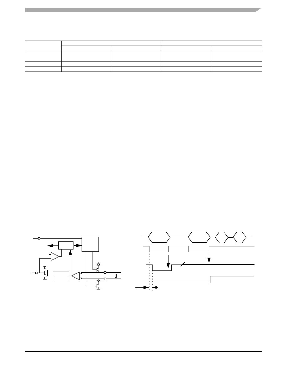
Figure 39. RXD Path Simplified Schematic, RXD Short to VDD Detection
Implementation for Detection
The implementation senses the RXD output voltage at
each low to high transition of the differential receiver.
Excluding the internal propagation delay, the RXD output
should be low when the differential receiver is low. When an
external short to VDD at the RXD output, RXD will be tied to
a high level and can be detected at the next low to high
transition of the differential receiver.
As soon as the RXD permanent recessive is detected, the
RXD driver is deactivated.
L5 (threshold VDD -0.43 V)
H5 (threshold VDD -0.43 V)
L5 (threshold VDD -0.43 V)
H5 (threshold VDD -0.43 V)
No failure
0
CANL to 5.0 V
1
CANH to 5.0 V
1
0
1
Table 10. Failure Detection Truth Table
Failure Description
Driver Recessive State
Driver Dominant State
Lg (threshold 1.75 V)
Hg (threshold 1.75 V)
Lg (threshold 1.75 V)
Hg (threshold 1.75 V)
CANH
CANL
Diff
VDD
Rxsense
RXD driver
RXD
TXD
TXD driver
60
VDD
Logic
Diag
CANL&H
Diff output
RXD output
RXD short to VDD
Prop delay
RXD flag
RXD flag latched
VDD/2
Sampling
The RXD flag is not the RXPR bit in the LPC register, and neither is the CANF in the INTR register.
相关PDF资料 |
PDF描述 |
|---|---|
| MCZ33903BD3EK | IC SBC CAN HS 3.3V 32SOIC |
| MCZ33905BS5EKR2 | IC SBC CAN HS 5.0V 32SOIC |
| MCZ33905BS5EK | IC SBC CAN HS 5.0V 32SOIC |
| MS27473T24A29P | CONN PLUG 29POS STRAIGHT W/PINS |
| VE-B50-IW-F3 | CONVERTER MOD DC/DC 5V 100W |
相关代理商/技术参数 |
参数描述 |
|---|---|
| MCZ33903BD5EKR2 | 功能描述:CAN 接口集成电路 SBC W/HIGH SPEED CAN 5V RoHS:否 制造商:Texas Instruments 类型:Transceivers 工作电源电压:5 V 电源电流: 工作温度范围:- 40 C to + 85 C 封装 / 箱体:SOIC-8 封装:Tube |
| MCZ33903BD5R2 | 制造商:FREESCALE 制造商全称:Freescale Semiconductor, Inc 功能描述:SBC Gen2 with CAN High Speed and LIN Interface |
| MCZ33903BS3EK | 功能描述:CAN 接口集成电路 Canvas 32 SL (3.3V) RoHS:否 制造商:Texas Instruments 类型:Transceivers 工作电源电压:5 V 电源电流: 工作温度范围:- 40 C to + 85 C 封装 / 箱体:SOIC-8 封装:Tube |
| MCZ33903BS3EKR2 | 功能描述:CAN 接口集成电路 Canvas 32 SL (3.3V) RoHS:否 制造商:Texas Instruments 类型:Transceivers 工作电源电压:5 V 电源电流: 工作温度范围:- 40 C to + 85 C 封装 / 箱体:SOIC-8 封装:Tube |
| MCZ33903BS3R2 | 制造商:FREESCALE 制造商全称:Freescale Semiconductor, Inc 功能描述:SBC Gen2 with CAN High Speed and LIN Interface |
发布紧急采购,3分钟左右您将得到回复。