- 您现在的位置:买卖IC网 > PDF目录189259 > NT2GT72U4PD0BV-3C (NANYA TECHNOLOGY CORP) 256M X 72 DDR DRAM MODULE, 0.45 ns, DMA240 PDF资料下载
参数资料
| 型号: | NT2GT72U4PD0BV-3C |
| 厂商: | NANYA TECHNOLOGY CORP |
| 元件分类: | DRAM |
| 英文描述: | 256M X 72 DDR DRAM MODULE, 0.45 ns, DMA240 |
| 封装: | ROHS COMPLIANT, DIMM-240 |
| 文件页数: | 9/27页 |
| 文件大小: | 648K |
| 代理商: | NT2GT72U4PD0BV-3C |
第1页第2页第3页第4页第5页第6页第7页第8页当前第9页第10页第11页第12页第13页第14页第15页第16页第17页第18页第19页第20页第21页第22页第23页第24页第25页第26页第27页
NT1GT72U89D0BV / NT2GT72U4PD0BV / NT4GT72U4ND0BV
NT2GT72U8PD0BV
1GB: 128M x 72 / 2GB: 256M x 72 / 4GB: 512M x 72
PC2-5300 / PC3-6400
Registered DDR2 SDRAM DIMM
REV 1.1
17
01/2009
NANYA TECHNOLOGY CORP.
NANYA TECHNOLOGY CORP. reserves the right to change Products and Specifications without notice.
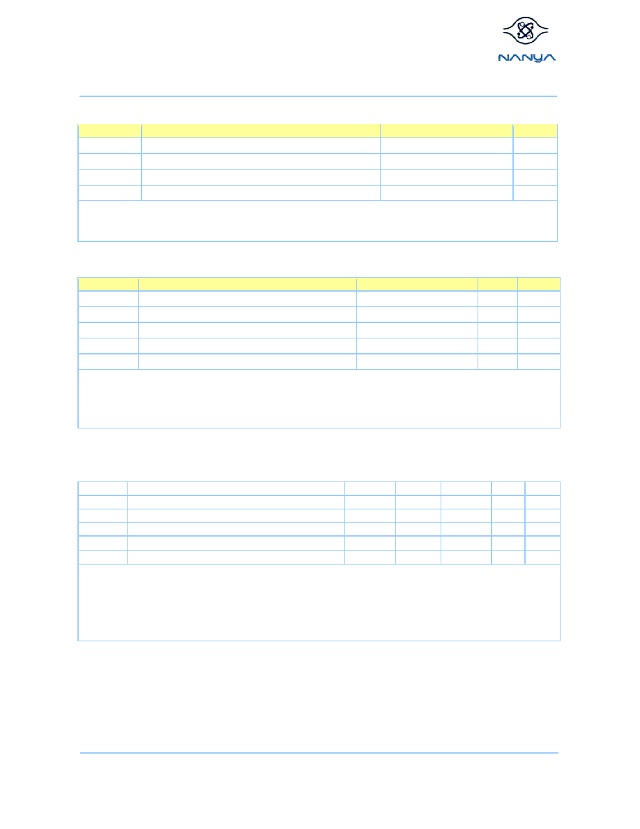
Absolute Maximum Ratings
Symbol
Parameter
Rating
Units
VIN, VOUT
Voltage on I/O pins relative to VSS
-0.5 to 2.3
V
VDD
Voltage on VDD supply relative to VSS
-1.0 to 2.3
V
VDDQ
Voltage on VDDQ supply relative to VSS
-0.5 to 2.3
V
VDDL
Voltage on VDDL supply relative to VSS
-0.5 to 2.3
V
Note: Stresses greater than those listed under “Absolute Maximum Ratings” may cause permanent damage to the device. This is stress
rating only, and functional operation of the device at these or any other conditions above those indicated in the operational
sections of this specification is not implied. Exposure to absolute maximum rating conditions for extended periods may affect
reliability.
Environmental Parameters
Symbol
Parameter
Rating
Units
Note
TOPR
Operating temperature (ambient)
See Note
3
HOPR
Operating Humidity (relative)
10 to 90
%
1
TOPR
Storage temperature
-50 to 100
°C
1
HOPR
Storage humidity (without condensation)
5 to 95
%
1
PBAR
Short Circuit Output Current
105 to 69
K Pascal
1,2
Note:
1. Stresses greater than those listed may cause permanent damage to the device. This is a stress rating only, and device functional
operation at or above the conditions indicated is not implied. Exposure to absolute maximum rating conditions for extended periods
may affect reliability.
2. Up to 9850 ft.
3. The designer must meet the case temperature specifications for individual module components.
DC Electrical Characteristics and Operating Conditions
(TCASE = 0 °C ~ 85 °C; VDDQ = 1.8V ± 0.1V; VDD = 1.8V ± 0.1V, See AC Characteristics)
Symbol
Parameter
Min.
Typ.
Max.
Units
Notes
VDD
Supply Voltage
1.7
1.8
1.9
V
1
VDDQ
Supply Voltage for Output
1.7
1.8
1.9
V
5
VDDL
Supply Voltage for DLL
1.7
1.8
1.9
V
1, 5
VREF
Input Reference Voltage
0.49
VDDQ
0.5
VDDQ
0.51
VDDQ
V
2, 3
VTT
Termination Voltage
VREF – 0.04
VREF
VDDQ + 0.04
V
4
Note:
1. There is no specific device VDD supply voltage requirement for SSTL_18 compliance. However under all conditions VDDQ must be
less than or equal to VDD.
2. The value of VREF may be selected by the user to provide optimum noise margin in the system. Typically the value of VREF is
expected to be about 0.5 x VDDQ of the transmitting device and VREF is expected to track variations in VDDQ.
3. Peak to peak ac noise on VREF may not exceed +/-2% VREF (dc).
4. VTT of transmitting device must track VREF of receiving device.
5. VDDQ tracks with VDD, VDDL tracks with VDD. AC parameters are measured with VDD, VDDQ and VDDDL tied together
相关PDF资料 |
PDF描述 |
|---|---|
| NT512T64U88B0BY-3C | 64M X 64 DDR DRAM MODULE, 0.5 ns, DMA240 |
| NT56V6620C0T-75 | SYNCHRONOUS DRAM, PDSO54 |
| NT5CB256M4AN-BF | DDR DRAM, PBGA78 |
| NT5DS64M8BF-6KI | DDR DRAM, PBGA60 |
| NT5SE8M16DS-6K | 8M X 16 SYNCHRONOUS DRAM, 5 ns, PDSO54 |
相关代理商/技术参数 |
参数描述 |
|---|---|
| NT2H0301F0DTL,125 | 功能描述:RFID应答器 RoHS:否 制造商:NXP Semiconductors 存储容量: 工作温度范围: 安装风格: 封装 / 箱体: 封装:Reel |
| NT2H0301F0DTP,118 | 制造商:NXP Semiconductors 功能描述:NT2H0301F0DTP - Tape and Reel 制造商:NXP Semiconductors 功能描述:PHANT2H0301F0DTP,118 NFC FORUM TYPE 2 TA 制造商:NXP Semiconductors 功能描述:IC SMART TAG NFC TYPE 2 8HWSON 制造商:NXP Semiconductors 功能描述:NT2H0301F0DTP/HWSON8/REEL13// |
| NT2H0301F0DTP,147 | 制造商:NXP Semiconductors 功能描述:CHIPSET |
| NT2H0301F0DUDV | 制造商:NXP Semiconductors 功能描述:CHIPSET |
| NT2H0301G0DUD,005 | 制造商:NXP Semiconductors 功能描述:NT2H0301G0DUD/UNCASED/FOIL// - Gel-pak, waffle pack, wafer, diced wafer on film 制造商:NXP Semiconductors 功能描述:IC SMART TAG NFC TYPE 2 UNCASED |
发布紧急采购,3分钟左右您将得到回复。