- 您现在的位置:买卖IC网 > Datasheet目录508 > SI1563EDH-T1-GE3 (Vishay Siliconix)MOSFET N/P-CH 20V SC70-6 Datasheet资料下载
参数资料
| 型号: | SI1563EDH-T1-GE3 |
| 厂商: | Vishay Siliconix |
| 文件页数: | 11/14页 |
| 文件大小: | 0K |
| 描述: | MOSFET N/P-CH 20V SC70-6 |
| 标准包装: | 3,000 |
| 系列: | TrenchFET® |
| FET 型: | N 和 P 沟道 |
| FET 特点: | 逻辑电平门 |
| 漏极至源极电压(Vdss): | 20V |
| 电流 - 连续漏极(Id) @ 25° C: | 1.13A,880mA |
| 开态Rds(最大)@ Id, Vgs @ 25° C: | 280 毫欧 @ 1.13A,4.5V |
| Id 时的 Vgs(th)(最大): | 450mV @ 100µA |
| 闸电荷(Qg) @ Vgs: | 1nC @ 4.5V |
| 功率 - 最大: | 570mW |
| 安装类型: | * |
| 封装/外壳: | 6-TSSOP,SC-88,SOT-363 |
| 供应商设备封装: | SC-70-6 |
| 包装: | 带卷 (TR) |
�� �
�
�AN816�
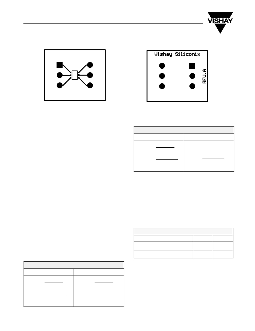
�Vishay� Siliconix�
�S1�
�G1�
�D2�
�Front� of� Board� SC70-6�
�SC70� ?� 6� DUAL�
�D1�
�G2�
�S2�
�Back� of� Board� SC70-6�
�vishay.com�
�FIGURE� 3.�
�THERMAL� PERFORMANCE�
�Junction-to-Foot� Thermal� Resistance�
�(the� Package� Performance)�
�COOPER LEADFRAM� E�
�Room� Ambient� 25� _� C�
�Elevated� Ambient� 60� _� C�
�R� q� JA�
�R� q� JA�
�P� D� +� 150� C� o� *� 60� C�
�o�
�o�
�P� D� +� 150� C� o� *� 25� C�
�Thermal� performance� for� the� dual� SC-70� 6-pin� package� is�
�measured� as� junction-to-foot� thermal� resistance,� in� which� the�
�“foot”� is� the� drain� lead� of� the� device� as� it� connects� with� the�
�body.� The� junction-to-foot� thermal� resistance� for� this� device� is�
�typically� 80� _� C/W,� with� a� maximum� thermal� resistance� of�
�approximately� 100� _� C/W.� This� data� compares� favorably� with�
�another� compact,� dual-channel� package� –� the� dual� TSOP-6� –�
�which� features� a� typical� thermal� resistance� of� 75� _� C/W� and� a�
�maximum� of� 90� _� C/W.�
�Power� Dissipation�
�The� typical� R� θ� JA� for� the� dual-channel� 6-pin� SC-70� with� a�
�copper� leadframe� is� 224� _� C/W� steady-state,� compared� to�
�413� _� C/W� for� the� Alloy� 42� version.� All� figures� are� based� on� the�
�1-inch� 2� FR4� test� board.� The� following� example� shows� how� the�
�thermal� resistance� impacts� power� dissipation� for� the� dual� 6-pin�
�SC-70� package� at� varying� ambient� temperatures.�
�T� J(max)� *� T� A� T� J(max)� *� T� A�
�P� D� +� P� D� +�
�o� o�
�224� C� W� 224� C� W�
�P� D� +� 558� mW� P� D� +� 402� mW�
�Although� they� are� intended� for� low-power� applications,�
�devices� in� the� 6-pin� SC-70� dual-channel� configuration� will�
�handle� power� dissipation� in� excess� of� 0.5� W.�
�TESTING�
�To� further� aid� the� comparison� of� copper� and� Alloy� 42�
�leadframes,� Figures� 4� and� 5� illustrate� the� dual-channel� 6-pin�
�SC-70� thermal� performance� on� two� different� board� sizes� and�
�pad� patterns.� The� measured� steady-state� values� of� R� θ� JA� for�
�the� dual� 6-pin� SC-70� with� varying� leadframes� are� as� follows:�
�LITTLE FOOT 6-PIN SC-7� 0�
�Alloy� 42� Copper�
�1)� Minimum� recommended� pad� pattern� on�
�the� EVB� board� (see� Figure� 3).�
�518� _� C/W�
�344� _� C/W�
�Alloy� 42� Leadframe�
�2)� Industry� standard� 1-inch� 2� PCB� with�
�maximum� copper� both� sides.�
�413� _� C/W�
�224� _� C/W�
�R� q� JA�
�R� q� JA�
�P� D� +� 150� C� o� *� 25� C�
�P� D� +� 150� C� o� *� 60� C�
�ALLOY� 42� LEADFRAME�
�Room� Ambient� 25� _� C�
�T� J(max)� *� T� A�
�P� D� +�
�o� o�
�413� C� W�
�P� D� +� 303� mW�
�www.vishay.com�
�2�
�Elevated� Ambient� 60� _� C�
�T� J(max)� *� T� A�
�P� D� +�
�o� o�
�413� C� W�
�P� D� +� 218� mW�
�The� results� indicate� that� designers� can� reduce� thermal�
�resistance� (� θ� JA)� by� 34%� simply� by� using� the� copper� leadframe�
�device� as� opposed� to� the� Alloy� 42� version.� In� this� example,� a�
�174� _� C/W� reduction� was� achieved� without� an� increase� in� board�
�area.� If� an� increase� in� board� size� is� feasible,� a� further� 120� _� C/W�
�reduction� can� be� obtained� by� utilizing� a� 1-inch� 2� .� PCB� area.�
�The� Dual� copper� leadframe� versions� have� the� following� suffix:�
�Dual:� Si19xxEDH�
�Compl.:� Si15xxEDH�
�Document� Number:� 71405�
�12-Dec-03�
�相关PDF资料 |
PDF描述 |
|---|---|
| SI1900DL-T1-E3 | MOSFET N-CH DUAL 30V SC70-6 |
| SI1902DL-T1-GE3 | MOSFET N-CH G-S 20V DUAL SC-70-6 |
| SI1926DL-T1-E3 | MOSF N CH DUAL D-S 60V SC-70-6 |
| SI1967DH-T1-E3 | MOSFET 2P-CH 20V 1.3A SC70-6 |
| SI1970DH-T1-GE3 | MOSFET N-CH DUAL 30V SC70-6 |
相关代理商/技术参数 |
参数描述 |
|---|---|
| SI15-K30-AN6 | 制造商:TURCK Inc 功能描述:Sensor, Inductive, 3 wire DC, NPN, 30mm Slot Sensor,Potted-in Cable |
| SI15-K30-AP6 | 制造商:TURCK Inc 功能描述:SI15-K30-AP6 |
| SI15-K30-AP6X | 制造商:TURCK Inc 功能描述:M1605001 |
| SI15-K30-AZ3 | 制造商:TURCK Inc 功能描述:M1306900 |
| SI15-K30-Y1 | 制造商:TURCK Inc 功能描述:SI15-K30-Y1 |
发布紧急采购,3分钟左右您将得到回复。