- 您现在的位置:买卖IC网 > PDF目录98143 > ST10F168-Q2 (STMICROELECTRONICS) 16-BIT, FLASH, 25 MHz, MICROCONTROLLER, PQFP144 PDF资料下载
参数资料
| 型号: | ST10F168-Q2 |
| 厂商: | STMICROELECTRONICS |
| 元件分类: | 微控制器/微处理器 |
| 英文描述: | 16-BIT, FLASH, 25 MHz, MICROCONTROLLER, PQFP144 |
| 封装: | 28 X 28 MM, PLASTIC, QFP-144 |
| 文件页数: | 31/76页 |
| 文件大小: | 483K |
| 代理商: | ST10F168-Q2 |
第1页第2页第3页第4页第5页第6页第7页第8页第9页第10页第11页第12页第13页第14页第15页第16页第17页第18页第19页第20页第21页第22页第23页第24页第25页第26页第27页第28页第29页第30页当前第31页第32页第33页第34页第35页第36页第37页第38页第39页第40页第41页第42页第43页第44页第45页第46页第47页第48页第49页第50页第51页第52页第53页第54页第55页第56页第57页第58页第59页第60页第61页第62页第63页第64页第65页第66页第67页第68页第69页第70页第71页第72页第73页第74页第75页第76页
ST10F168
37/76
17 - SYSTEM RESET
System reset initializes the MCU in a predefined
state. There are five ways to activate a reset state.
The system start-up configuration is different for
each case as shown in Table 21.
17.1 - Asynchronous Reset (Long Hardware
Reset)
An asynchronous reset is triggered when RSTIN
pin is pulled low while VPP pin is at low level. Then
the MCU is immediately forced in reset default
state. It pulls low RSTOUT pin, it cancels pending
internal hold states if any, it waits for any internal
access cycles to finish, it aborts external bus cycle,
it switches buses (data, address and control sig-
nals) and I/O pin drivers to high-impedance, it pulls
high Port0 pins and the reset sequence starts.
Power-on Reset
The asynchronous reset must be used during the
power-on of the MCU. Depending on crystal fre-
quency, the on-chip oscillator needs about 10ms
to 50ms to stabilize. The logic of the MCU does
not need a stabilized clock signal to detect an
asynchronous reset, so it is suitable for power-on
conditions. To ensure a proper reset sequence,
the RSTIN pin and the VPP pin must be held at low
level until the MCU clock signal is stabilized and
the system configuration value on Port0 is settled.
Hardware Reset
The asynchronous reset must be used to recover
from catastrophic situations of the application. It
may be triggerred by the hardware of the applica-
tion. Internal hardware logic and application cir-
cuitry are described in Reset circuitry chapter and
Figures 12, 13 and 14.
Exit of Asynchrounous Reset State
When the RSTIN pin is pulled high, the MCU
restarts. The system configuration is latched from
Port0 and ALE, RD and R/W pins are driven to their
inactive level. The MCU starts program execution
from memory location 00’0000h in code segment 0.
This starting location will typically point to the gen-
eral initialization routine. Timing of asynchronous
reset sequence are summarized in Figure 9.
Note
1. RSTIN rising edge to internal latch of Port0 is 3CPU clock cycles if the PLL is bypassed and the prescaler is on (f CPU =f XTAL /2),
else it is 4 CPU clock cycles.
Table 21 : Reset event definition
Reset Source
Short-cut
Conditio ns
Power-on reset
PONR
Power-on
Long Hardware reset (asynchronous reset)
LHWR
t RSTIN > 1032 TCL
Short Hardware reset (synchronous reset)
SHWR
4 TCL < t RSTIN < 1032 TCL
Watchdog Timer reset
WDTR
WDT overflow
Software reset
SWR
SRST execution
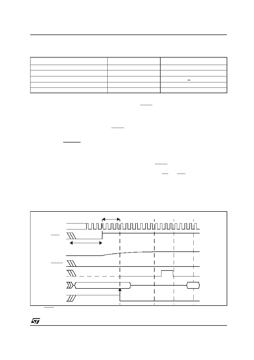
Figure 9 : Asynchronous Reset Timing
3or 4 CPU Clock1
CPU Clock
RSTIN
Asynchronous
Reset Condition
VPP
RSTOUT
ALE
Port0
Reset Configuration
INST #1
Internal
Reset
Signal
Latching point of Port0
for systemstart-up
configuration
相关PDF资料 |
PDF描述 |
|---|---|
| ST10F168-Q3 | 16-BIT, FLASH, 25 MHz, MICROCONTROLLER, PQFP144 |
| ST10F252M-4T3 | 16-BIT, FLASH, 40 MHz, RISC MICROCONTROLLER, PQFP100 |
| ST10F269DIETR | 16-BIT, FLASH, 32 MHz, MICROCONTROLLER, UUC |
| ST10F269Z2Q3 | 16-BIT, FLASH, 40 MHz, MICROCONTROLLER, PQFP144 |
| ST10F269Z2Q6 | 16-BIT, FLASH, 40 MHz, MICROCONTROLLER, PQFP144 |
相关代理商/技术参数 |
参数描述 |
|---|---|
| ST10F168Q3 | 制造商:STMicroelectronics 功能描述:MicroController, 16-Bit, 144 Pin, Plastic, QFP |
| ST10F168-Q3 | 制造商:STMicroelectronics 功能描述:MicroController, 16-Bit, 144 Pin, Plastic, QFP |
| ST10F168-Q6 | 制造商:STMICROELECTRONICS 制造商全称:STMicroelectronics 功能描述:16-BIT MCU WITH 256K BYTE FLASH MEMORY AND 8K BYTE RAM |
| ST10F168SQ3 | 功能描述:16位微控制器 - MCU 256K Flash 8K RAM RoHS:否 制造商:Texas Instruments 核心:RISC 处理器系列:MSP430FR572x 数据总线宽度:16 bit 最大时钟频率:24 MHz 程序存储器大小:8 KB 数据 RAM 大小:1 KB 片上 ADC:Yes 工作电源电压:2 V to 3.6 V 工作温度范围:- 40 C to + 85 C 封装 / 箱体:VQFN-40 安装风格:SMD/SMT |
| ST10F168SQ6 | 功能描述:16位微控制器 - MCU 256K Flash 8K RAM RoHS:否 制造商:Texas Instruments 核心:RISC 处理器系列:MSP430FR572x 数据总线宽度:16 bit 最大时钟频率:24 MHz 程序存储器大小:8 KB 数据 RAM 大小:1 KB 片上 ADC:Yes 工作电源电压:2 V to 3.6 V 工作温度范围:- 40 C to + 85 C 封装 / 箱体:VQFN-40 安装风格:SMD/SMT |
发布紧急采购,3分钟左右您将得到回复。