- 您现在的位置:买卖IC网 > PDF目录69378 > ST7PL35F2MCXXXRE (STMICROELECTRONICS) 8-BIT, MROM, 8 MHz, MICROCONTROLLER, PDSO20 PDF资料下载
参数资料
| 型号: | ST7PL35F2MCXXXRE |
| 厂商: | STMICROELECTRONICS |
| 元件分类: | 微控制器/微处理器 |
| 英文描述: | 8-BIT, MROM, 8 MHz, MICROCONTROLLER, PDSO20 |
| 封装: | 0.300 INCH, ROHS COMPLIANT, PLASTIC, SOP-20 |
| 文件页数: | 17/168页 |
| 文件大小: | 2955K |
| 代理商: | ST7PL35F2MCXXXRE |
第1页第2页第3页第4页第5页第6页第7页第8页第9页第10页第11页第12页第13页第14页第15页第16页当前第17页第18页第19页第20页第21页第22页第23页第24页第25页第26页第27页第28页第29页第30页第31页第32页第33页第34页第35页第36页第37页第38页第39页第40页第41页第42页第43页第44页第45页第46页第47页第48页第49页第50页第51页第52页第53页第54页第55页第56页第57页第58页第59页第60页第61页第62页第63页第64页第65页第66页第67页第68页第69页第70页第71页第72页第73页第74页第75页第76页第77页第78页第79页第80页第81页第82页第83页第84页第85页第86页第87页第88页第89页第90页第91页第92页第93页第94页第95页第96页第97页第98页第99页第100页第101页第102页第103页第104页第105页第106页第107页第108页第109页第110页第111页第112页第113页第114页第115页第116页第117页第118页第119页第120页第121页第122页第123页第124页第125页第126页第127页第128页第129页第130页第131页第132页第133页第134页第135页第136页第137页第138页第139页第140页第141页第142页第143页第144页第145页第146页第147页第148页第149页第150页第151页第152页第153页第154页第155页第156页第157页第158页第159页第160页第161页第162页第163页第164页第165页第166页第167页第168页
Obsolete
- Obsolete
Product(s)
ST7L34, ST7L35, ST7L38, ST7L39
113/168
LINSCI
SERIAL COMMUNICATION INTERFACE (LIN Mode) (cont’d)
SCICR2 register is set, the LHDM bit selects the
Wake-Up method (replacing the WAKE bit).
0: LIN Synch Break Detection Method
1: LIN Identifier Field Detection Method
Bit 2 = LHIE LIN Header Interrupt Enable
This bit is set and cleared by software. It is only us-
able in LIN Slave mode.
0: LIN Header Interrupt is inhibited.
1: An SCI interrupt is generated whenever
LHDF = 1.
Bit 1 = LHDF LIN Header Detection Flag
This bit is set by hardware when a LIN Header is
detected and cleared by a software sequence (an
access to the SCISR register followed by a read of
the SCICR3 register). It is only usable in LIN Slave
mode.
0: No LIN Header detected.
1: LIN Header detected.
Notes: The header detection method depends on
the LHDM bit:
– If LHDM = 0, a header is detected as a LIN
Synch Break.
– If LHDM = 1, a header is detected as a LIN
Identifier, meaning that a LIN Synch Break
Field + a LIN Synch Field + a LIN Identifier
Field have been consecutively received.
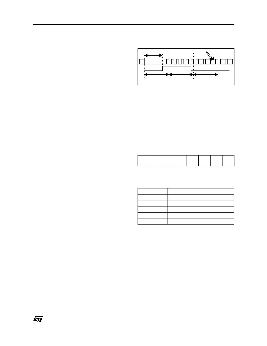
Bit 0 = LSF LIN Synch Field State
This bit indicates that the LIN Synch Field is being
analyzed. It is only used in LIN Slave mode. In
Auto Synchronization Mode (LASE bit = 1), when
the SCI is in the LIN Synch Field State it waits or
counts the falling edges on the RDI line.
It is set by hardware as soon as a LIN Synch Break
is detected and cleared by hardware when the LIN
Synch Field analysis is finished (see Figure 65).
This bit can also be cleared by software to exit LIN
Synch State and return to idle mode.
0: The current character is not the LIN Synch Field
1: LIN Synch Field State (LIN Synch Field under-
going analysis)
Figure 65. LSF Bit Set and Clear
LIN DIVIDER REGISTERS
LDIV is coded using the two registers LPR and LP-
FR. In LIN Slave mode, the LPR register is acces-
sible at the address of the SCIBRR register and
the LPFR register is accessible at the address of
the SCIETPR register.
LIN PRESCALER REGISTER (LPR)
Read/Write
Reset Value: 0000 0000 (00h)
LPR[7:0] LIN Prescaler (mantissa of LDIV)
These 8 bits define the value of the mantissa of the
LIN Divider (LDIV):
Caution: LPR and LPFR registers have different
meanings when reading or writing to them. Conse-
quently bit manipulation instructions (BRES or
BSET) should never be used to modify the
LPR[7:0] bits, or the LPFR[3:0] bits.
70
LPR7
LPR6
LPR5
LPR4
LPR3
LPR2
LPR1
LPR0
LPR[7:0]
Rounded Mantissa (LDIV)
00h
SCI clock disabled
01h
1
...
FEh
254
FFh
255
LIN Synch
Identifier
parity bits
Field
Break
11 dominant bits
LSF bit
相关PDF资料 |
PDF描述 |
|---|---|
| ST7PL35F2UA/XXXE | 8-BIT, MROM, 8 MHz, MICROCONTROLLER, QCC20 |
| ST7L35F2UA/XXXRE | 8-BIT, MROM, 8 MHz, MICROCONTROLLER, QCC20 |
| ST7L35F2UC/XXXRE | 8-BIT, MROM, 8 MHz, MICROCONTROLLER, QCC20 |
| ST7L39F2MC/XXXE | 8-BIT, MROM, 8 MHz, MICROCONTROLLER, PDSO20 |
| ST7L39F2UC/XXXRE | 8-BIT, MROM, 8 MHz, MICROCONTROLLER, QCC20 |
相关代理商/技术参数 |
参数描述 |
|---|---|
| ST7PLITE02F0U6TR | 制造商:STMICROELECTRONICS 制造商全称:STMicroelectronics 功能描述:8-BIT MICROCONTROLLER WITH SINGLE VOLTAGE FLASH MEMORY, DATA EEPROM, ADC, TIMERS, SPI |
| ST7PLITE02Y0B6 | 制造商:STMICROELECTRONICS 制造商全称:STMicroelectronics 功能描述:8-BIT MICROCONTROLLER WITH SINGLE VOLTAGE FLASH MEMORY, DATA EEPROM, ADC, TIMERS, SPI |
| ST7PLITE02Y0B6TR | 制造商:STMICROELECTRONICS 制造商全称:STMicroelectronics 功能描述:8-bit microcontroller with single voltage Flash memory, data EEPROM, ADC, timers, SPI |
| ST7PLITE02Y0M6 | 制造商:STMICROELECTRONICS 制造商全称:STMicroelectronics 功能描述:8-bit microcontroller with single voltage Flash memory, data EEPROM, ADC, timers, SPI |
| ST7PLITE02Y0M6TR | 制造商:STMICROELECTRONICS 制造商全称:STMicroelectronics 功能描述:8-bit microcontroller with single voltage Flash memory, data EEPROM, ADC, timers, SPI |
发布紧急采购,3分钟左右您将得到回复。