- 您现在的位置:买卖IC网 > PDF目录300164 > ZL50418GKG2 (CONEXANT SYSTEMS) DATACOM, LAN SWITCHING CIRCUIT, PBGA553 PDF资料下载
参数资料
| 型号: | ZL50418GKG2 |
| 厂商: | CONEXANT SYSTEMS |
| 元件分类: | 网络接口 |
| 英文描述: | DATACOM, LAN SWITCHING CIRCUIT, PBGA553 |
| 封装: | 37.50 X 37.50 MM, 2.33 MM HEIGHT, LEAD FREE, MS-034, HSBGA-553 |
| 文件页数: | 114/155页 |
| 文件大小: | 1928K |
| 代理商: | ZL50418GKG2 |
第1页第2页第3页第4页第5页第6页第7页第8页第9页第10页第11页第12页第13页第14页第15页第16页第17页第18页第19页第20页第21页第22页第23页第24页第25页第26页第27页第28页第29页第30页第31页第32页第33页第34页第35页第36页第37页第38页第39页第40页第41页第42页第43页第44页第45页第46页第47页第48页第49页第50页第51页第52页第53页第54页第55页第56页第57页第58页第59页第60页第61页第62页第63页第64页第65页第66页第67页第68页第69页第70页第71页第72页第73页第74页第75页第76页第77页第78页第79页第80页第81页第82页第83页第84页第85页第86页第87页第88页第89页第90页第91页第92页第93页第94页第95页第96页第97页第98页第99页第100页第101页第102页第103页第104页第105页第106页第107页第108页第109页第110页第111页第112页第113页当前第114页第115页第116页第117页第118页第119页第120页第121页第122页第123页第124页第125页第126页第127页第128页第129页第130页第131页第132页第133页第134页第135页第136页第137页第138页第139页第140页第141页第142页第143页第144页第145页第146页第147页第148页第149页第150页第151页第152页第153页第154页第155页
ZL50418
Data Sheet
61
Zarlink Semiconductor Inc.
8.6
Shaper
Although traffic shaping is not a primary function of the ZL50418, the chip does implement a shaper for expedited
forwarding (EF). Our goal in shaping is to control the peak and average rate of traffic exiting the ZL50418. Shaping
is limited to the two Gigabit ports only, and only to class P6 (the second highest priority). This means that class P6
will be the class used for EF traffic. If shaping is enabled for P6, then P6 traffic must be scheduled using strict
priority. With reference to Table 7, only the middle two QoS configurations may be used.
Peak rate is set using a programmable whole number, no greater than 64. For example, if the setting is 32, then the
peak rate for shaped traffic is 32/64 * 1000 Mbps = 500 Mbps. Average rate is also a programmable whole number,
no greater than 64 and no greater than the peak rate. For example, if the setting is 16, then the average rate for
shaped traffic is 16/64 * 1000 Mbps = 250 Mbps. As a consequence of the above settings in our example, shaped
traffic will exit the ZL50418 at a rate always less than 500 Mbps and averaging no greater than 250 Mbps. See
Programming QoS Register application note for more information.
Also, when shaping is enabled, it is possible for a P6 queue to explode in length if fed by a greedy source. The
reason is that a shaper is by definition not work-conserving; that is, it may hold back from sending a packet even if
the line is idle. Though we do have global resource management, we do nothing to prevent this situation locally. We
assume SP traffic is policed at a prior stage to the ZL50418.
8.7
Rate Control
The ZL50418 provides a rate control function on its 10/100 M ports. This rate control function applies to the
outgoing traffic aggregate on each 10/100 M port. It provides a way of reducing the outgoing average rate below full
wire speed. Note that the rate control function does not shape or manipulate any particular traffic class.
Furthermore, though the average rate of the port can be controlled with this function, the peak rate will still be full
line rate.
Two principal parameters are used to control the average rate for a 10/100 M port. A port’s rate is controlled by
allowing, on average, M bytes to be transmitted every N microseconds. Both of these values are programmable.
The user can program the number of bytes in 8-byte increments and the time may be set in units of 10 ms.
The value of M/N will, of course, equal the average data rate of the outgoing traffic aggregate on the given
10/100 M port. Although there are many (M,N) pairs that will provide the same average data rate performance, the
smaller the time interval N, the “smoother” the output pattern will appear.
In addition to controlling the average data rate on a 10/100 M port, the rate control function also manages the
maximum burst size at wire speed. The maximum burst size can be considered the memory of the rate control
mechanism; if the line has been idle for a long time, to what extent can the port “make up for lost time” by
transmitting a large burst? This value is also programmable, measured in 8-byte increments.
Example: Suppose that the user wants to restrict Fast Ethernet port P’s average departure rate to 32 Mbps – 32%
of line rate – when the average is taken over a period of 10 ms. In an interval of 10 ms, exactly 40000 bytes can be
transmitted at an average rate of 32 Mbps.
So how do we set the parameters? The rate control parameters are contained in an internal RAM block accessible
through the CPU port (See Programming QoS Registers application note and Processor interface application note).
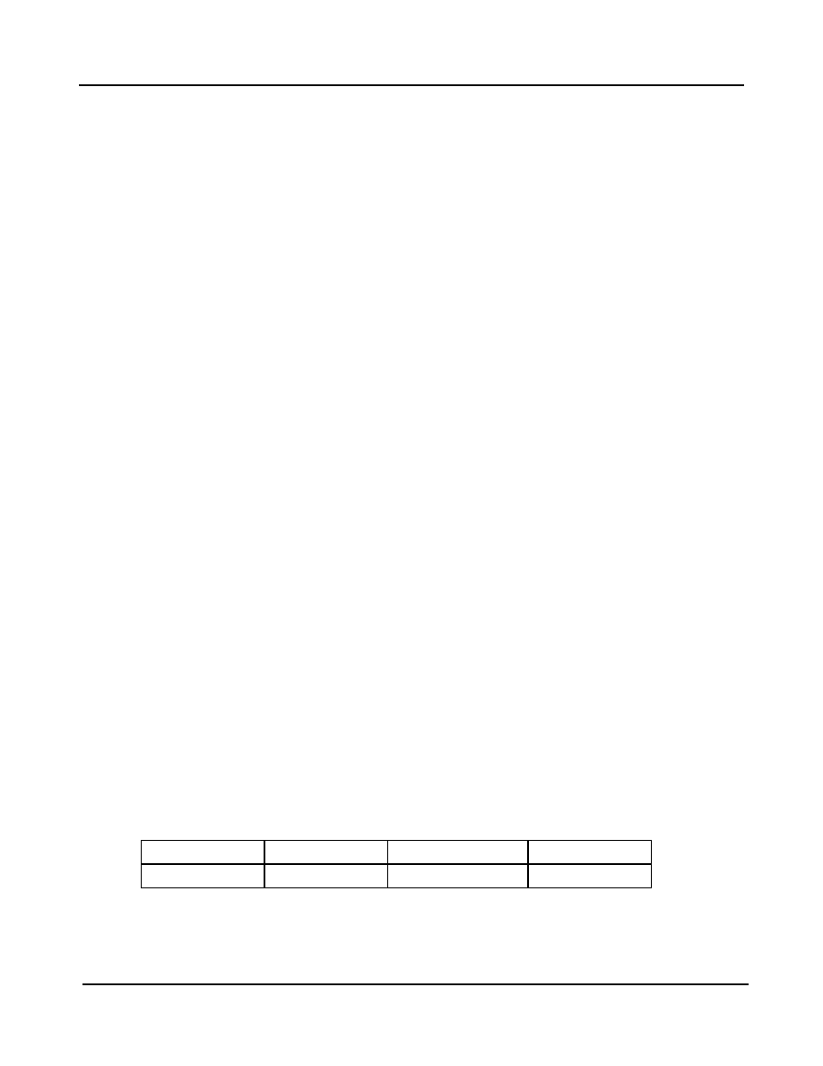
The data format is shown below.
As we indicated earlier, the number of bytes is measured in 8-byte increments, so the 16-bit field “Number of bytes”
should be set to 40000/8, or 5000. In addition, the time interval has to be indicated in units of 10 ms. Though we
want the average data rate on port P to be 32 Mbps when measured over an interval of 10 ms, we can also adjust
the maximum number of bytes that can be transmitted at full line rate in any single burst. Suppose we wish this limit
63:40
39:32
31:16
15:0
0
Time interval
Maximum burst size
Number of bytes
相关PDF资料 |
PDF描述 |
|---|---|
| ZL50418/GKC | DATACOM, LAN SWITCHING CIRCUIT, PBGA553 |
| ZL50418GKG2 | DATACOM, LAN SWITCHING CIRCUIT, PBGA553 |
| ZLW-2-B | 1 MHz - 1000 MHz RF/MICROWAVE DOUBLE BALANCED MIXER, 9.5 dB CONVERSION LOSS-MAX |
| ZMG71W | SINGLE COLOR LED, GREEN |
| ZMM5228/D1 | 3.9 V, 0.5 W, SILICON, UNIDIRECTIONAL VOLTAGE REGULATOR DIODE |
相关代理商/技术参数 |
参数描述 |
|---|---|
| ZL51B | 制造商:YEASHIN 制造商全称:YEASHIN 功能描述:500 mW DO-35 Hermetically Sealed Glass Zener Voltage Regulators |
| ZL56B | 制造商:YEASHIN 制造商全称:YEASHIN 功能描述:500 mW DO-35 Hermetically Sealed Glass Zener Voltage Regulators |
| ZL5V1B | 制造商:YEASHIN 制造商全称:YEASHIN 功能描述:500 mW DO-35 Hermetically Sealed Glass Zener Voltage Regulators |
| ZL5V6B | 制造商:YEASHIN 制造商全称:YEASHIN 功能描述:500 mW DO-35 Hermetically Sealed Glass Zener Voltage Regulators |
| ZL60001 | 制造商:ZARLINK 制造商全称:Zarlink Semiconductor Inc 功能描述:High speed 2.5 Gbps 850 nm VCSEL |
发布紧急采购,3分钟左右您将得到回复。